While manufacturing excellence ensures precast elements are produced to specification, installation excellence determines whether those superior elements deliver their intended performance in the structure. The Precast/Prestressed Concrete Institute's MNL-135 'Recommended Practice for Design, Manufacture and Installation of Connections and Electrical Boxes/Fittings in Precast Concrete' provides the definitive guidance for safe and successful precast installation. From the moment elements leave the manufacturing facility through rigging, transportation, on-site unloading, and final placement and connection, every step must be executed with precision. Installation failures can negate the quality achieved in the plant, compromise structural integrity, and create safety hazards. Proper implementation of MNL-135 protocols separates superior installation contractors from those who cut corners and face field problems.
Transportation: Protecting Elements from Damage
Precast elements begin their journey from the plant to the job site vulnerable to damage. Unlike cast-in-place concrete, field damage cannot be easily corrected. Transportation safety depends on proper bracing, support geometry, and driver training. Elements must be supported at the correct locations to avoid negative bending moments that could crack the concrete. Heavy double-tees, hollow-core planks, and single tees have specific support points determined by the manufacturer—these points must be located precisely on the transport vehicle. Point loads from improper support can exceed local bearing capacity and cause crushing or cracking. Long elements may experience vibration from road conditions if not properly dampened. Corner and edge impacts during loading or unloading can create visible spalling or hidden damage that weakens the element.
- Bracing design based on element geometry: Support points located at manufacturer-specified positions for moment control
- Dynamic loading analysis: Vehicles must have shock absorbers and suspension suitable for precast loads, particularly for long spans
- Securing methods: Straps, chains, or other restraint systems prevent lateral movement during transit
- Driver qualifications: Operators trained in handling precast, understanding load distribution, and recognizing potential damage
- Protection against weather: Uncovered elements may absorb water during transport, affecting appearance and early-age strength
Rigging Design: Engineering the Lift
Hoisting precast elements requires engineering rigging designs that account for the element weight, lifting point geometry, rope/hardware capacity, and dynamic effects. Poor rigging design has caused catastrophic failures—elements dropped, rigging hardware failure, or uncontrolled tilting. MNL-135 requires that lifting points be specifically designed during the manufacturing stage, cast into the element, and clearly identified. Temporary lifting inserts used during manufacturing are not suitable for final placement; permanent hardware must be provided. Each element must have its safe working load (SWL) and rigging instructions clearly marked. Rigging must account for dynamic loading—the actual force applied when lifting begins exceeds static weight. Dynamic amplification factors of 1.3-1.5 are typical for crane accelerations.
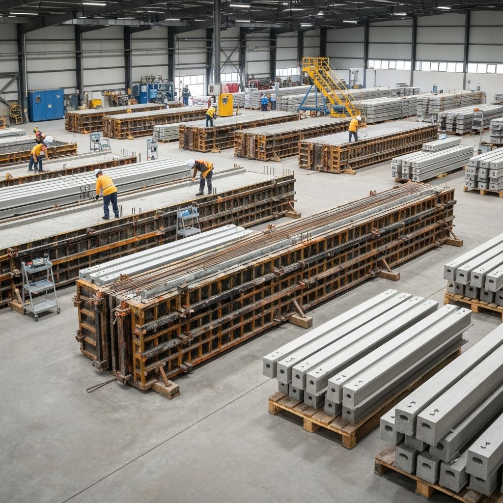
On-Site Unloading and Staging Safety
Site logistics determine whether elements are protected or damaged. Elements delivered by truck must be carefully unloaded using proper rigging, spotters, and coordinated procedures. Staging areas should provide stable ground, protection from weather, and clear identification of element positions. Elements stacked improperly can fail under load; bottom elements may crush if upper elements are placed carelessly. Air gaps between elements reduce bearing area and can cause localized stress. PCI MNL-135 provides stacking guidance specific to element type and strength. Temporary bracing during storage prevents elements from tilting or falling. Site safety requires trained riggers, communication protocols (hand signals or radios), and traffic control to prevent vehicles or personnel from interfering with hoisting operations.
- Rigging inspection: Visual inspection of all lifting hardware, hooks, and connections before each use
- Communication protocols: Standardized hand signals or radio coordination between crane operator, rigger, and spotters
- Temporary bracing: Elements must be braced to prevent movement, rotation, or tipping during storage and before final installation
- Ground preparation: Stable, level staging areas prevent elements from settling unevenly or tipping
- Weather protection: Covers prevent moisture absorption during storage, particularly important for elements with exposed reinforcement
Installation Sequence and Connection Design
The sequence in which elements are installed affects structural stability and accuracy. Early placement of key elements (usually bearing walls or columns) establishes the structural frame, allowing subsequent elements to be positioned accurately. Connections between elements must be designed to transfer all forces (vertical loads, lateral loads, and moments) between elements and to the supporting structure. Connection design is critical—undersized connections concentrate stress and can fail; poorly detailed connections create stress risers. Connections must accommodate manufacturing tolerances, field construction tolerances, and subsequent movements from loading and environmental effects.
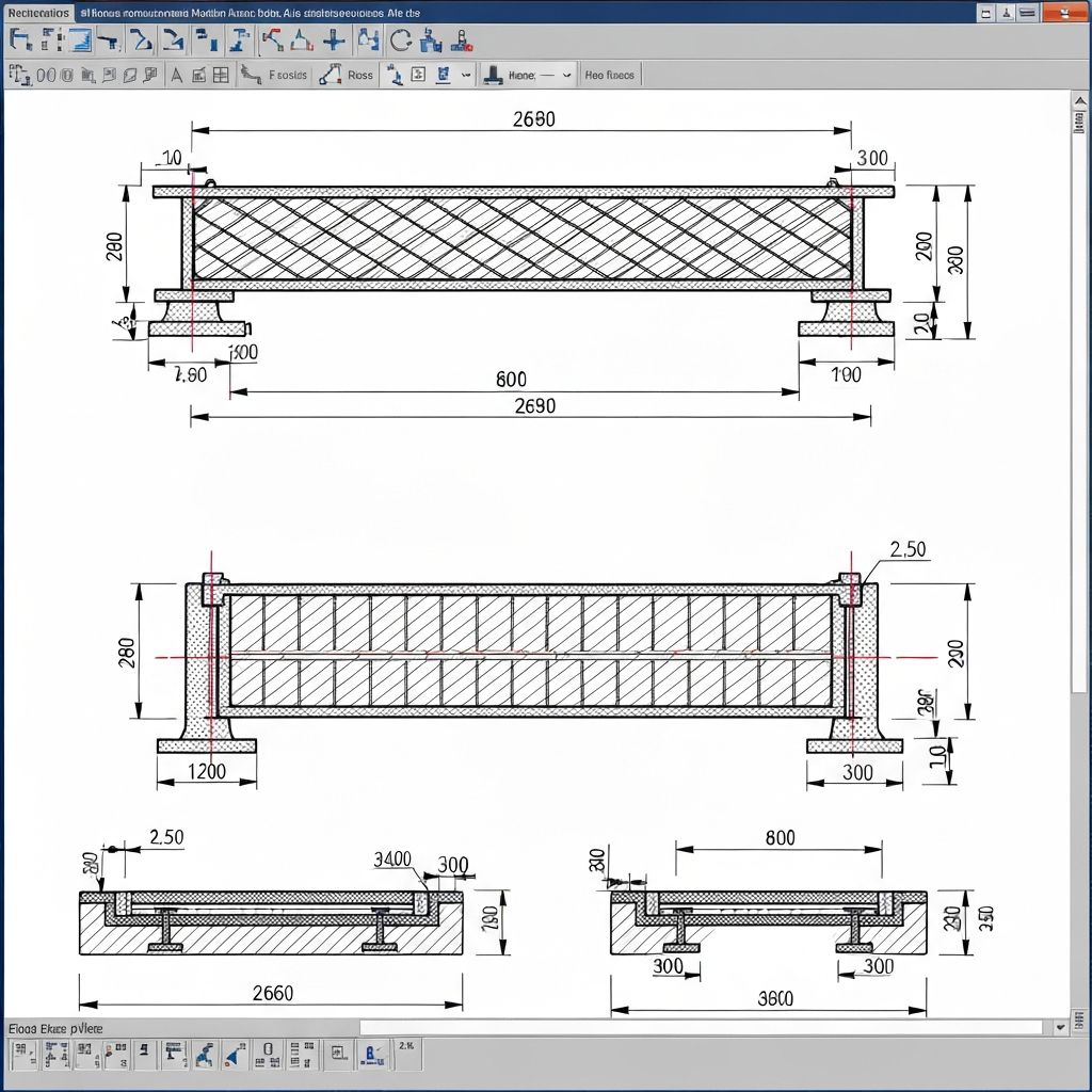
Field Connection Details and Tolerances
MNL-135 provides detailed guidance for designing connections that function reliably despite inevitable dimensional variations. Cast-in-place connection hardware (embed plates, corbels, seat angles) must be positioned precisely during manufacturing. Field connections (bolts, welds, grout) must accommodate assembly tolerances. A typical tolerance budget might allocate ±12mm for manufacturing and ±25mm for installation—total potential variation of ±37mm. If connections require ±10mm tolerance but 37mm variation is possible, connection failures will occur. Design solutions include adjustable connections with shims, slotted bolt holes, or designed grout pads that accommodate variation. The structural engineer and precast designer must coordinate to ensure connections work reliably in the field with anticipated tolerances.
- Embed position verification: Cast-in-place embeds must be located within ±12mm horizontal and ±6mm vertical per MNL-135
- Adjustable seat connections: Allow vertical adjustment through shim pads or adjustable bases
- Slotted bolt holes: Provide ±25mm horizontal adjustment for connection hardware
- Grout bedding: Controlled placement below elements on bearing pads distributes loads and accommodates surface irregularities
- Verification before connection: Each element position must be verified before final connections are made, allowing for corrections
Critical Installation Challenges and Expertise Required
Successful precast installation requires specialized knowledge and experience. First, element positioning accuracy determines whether subsequent connections will function as designed. Settlement, drift, or misalignment of early-installed elements compromises the entire structure. Second, connection assembly requires coordination of multiple trades—erection crew positioning elements, ironworker bolting connections, concrete crew grouting pads and connection details. Poor coordination causes delays and errors. Third, weather affects installation quality—rain during bolting operations can prevent welds or bolts from developing rated strength; frost exposure can affect grout development. Fourth, temporary bracing provides lateral stability while permanent connections are developed; inadequate bracing during installation can cause structural failures during wind events. Fifth, quality inspection during assembly verifies that connections are made correctly and loads can transfer as designed.
Connectivity and Inspection During Installation
MNL-135 emphasizes the need for inspection and verification at each installation stage. Before an element is fully connected and loaded, its position must be verified to be within tolerance. Connection assembly (bolting, welding, grouting) must follow engineering specifications and industry standards. Welds must be inspected for size, extent, and quality; bolts must be torqued to specification; grout must achieve design strength before loads are applied. Some installations use temporary shoring or bracing during connection assembly—this temporary support must not be removed until permanent connections are fully developed and verified. Quality documentation of installation procedures, inspections, and verification supports project completion and supports warranty claims if issues arise.
Design Coordination: Manufacturing and Installation Integration
Successful precast projects require close coordination between structural designers, precast manufacturing engineers, and installation contractors during the design phase. Rigging points, embed locations, connection details, and temporary bracing must be designed during planning, not improvised in the field. Drawings must clearly show rigging details, embed positions, connection sequences, temporary bracing requirements, and inspection checkpoints. Manufacturing quality (covered in PCI MNL-116) is necessary but not sufficient—without proper installation (MNL-135), superior manufactured elements cannot perform as designed. The structural engineer, precast designer, and installation contractor must work collaboratively to ensure the complete system functions reliably.
Conclusion
Precast concrete installation excellence is not improvisation—it requires systematic design, rigorous execution, and continuous verification. PCI MNL-135 provides the framework; project teams must implement it with discipline and expertise. VSG's consulting experience spans precast system design, installation sequencing, connection design optimization, and field failure investigation. Whether developing comprehensive precast installation specifications, reviewing connection details for constructability, or investigating field installation issues, our engineering expertise ensures superior precast performance. Contact VSG to discuss precast installation strategies, connection design challenges, or field problem resolution.
Related Testing Services
- Bolt Tension Verification
- Weld Quality Inspection
- Grout Strength Testing
- Connection Load Testing
- Element Position Verification
- Alignment Tolerance Checks
Applicable Standards
Professional Engineering Support
This testing and verification work is part of comprehensive construction management and quality assurance services provided by our architectural and engineering consulting team. We support project management, quality control, and commissioning across military, nuclear, infrastructure, and commercial sectors.
Request Engineering Services