EN 1992-1-1 Section 9.2.1 establishes mandatory minimum reinforcement requirements ensuring that when tensile stress in concrete exceeds tensile strength, bonded reinforcement controls crack distribution by producing numerous fine cracks rather than single wide failure crack. Minimum reinforcement represents a fundamental quality assurance requirement in reinforced concrete design, protecting against brittle failure and ensuring structures maintain serviceability following first cracking. The specification of minimum reinforcement is a critical construction and quality control checkpoint, requiring engineers and contractors to verify that designs provide adequate bonded reinforcement and that installed reinforcement meets design specifications. Value engineering must never compromise minimum reinforcement requirements, as these represent material cost-effective insurance against catastrophic cracking failure. Understanding minimum reinforcement calculation procedures, quality assurance verification methods, construction detailing requirements, and compliance assessment is essential for structural engineers, contractors, and quality control personnel responsible for concrete structure design and construction.
Fundamental Principle of Minimum Reinforcement
EN 1992-1-1 Section 9.2.1.1 establishes the fundamental principle: bonded reinforcement must develop sufficient force at the tensile strength of concrete to control crack distribution. When flexural tensile stress would exceed the mean concrete tensile strength f_ctm in uncracked concrete, reinforcement must provide enough area to prevent brittle failure. The theoretical basis involves: when first crack initiates at stress f_ctm, if unbonded, crack width would increase rapidly as load increases (tension-stiffening effect). Bonded reinforcement bridges the crack, transferring stress through bond to concrete on both sides, preventing stress concentration and limiting crack width growth.
Quality assurance requires verifying that:
- •Reinforcement is provided in sections where design indicates tensile stress exceeds f_ctm
- •Reinforcement quantity meets calculated minimum
- •Reinforcement bond characteristics (deformed bars, adequate cover, proper anchorage) enable effective stress transfer
- •Construction quality control confirms reinforcement placement matches design drawings
Value engineering must never eliminate minimum reinforcement to achieve cost savings, as this represents catastrophic design failure. Instead, cost optimization should focus on efficiency of reinforcement layout, bar sizes, and spacing within minimum requirements.
Minimum Reinforcement Calculation Formula and Parameters
EN 1992-1-1 Section 9.2.1.1 provides the formula for minimum reinforcement area:
A_s,min = k_c · k · f_ct,eff · A_ct / f_yk
where:
• k_c—coefficient reflecting stress distribution (typically k_c = 0.4 for bending with tension on one face, k_c = 1.0 for pure tension or composite sections)
- •k—coefficient reflecting neutral axis position (k = 1.0 for members failing in tension, k = (h - x)/d for bending where x is neutral axis depth)
- •f_ct,eff—effective mean tensile strength of concrete (typically f_ctm from EN 1992 expressions or measured values)
- •A_ct—effective tension area of concrete section (typically the tension flange width times effective depth, or entire section for pure tension)
- •f_yk—characteristic yield strength of reinforcement (typically 500 MPa for modern reinforcement)
The formula ensures that reinforcement force A_s · f_yk at yield equals k_c · k · f_ct,eff · A_ct, the force that would cause cracking. Quality control must verify that calculated A_s,min is supplied and properly anchored in construction. Common simplifications per Section 9.2.1.1 include: minimum reinforcement for flexural tension ≈ 0.26 (f_ctm / f_yk) · b_t · d where b_t is tension zone width; minimum reinforcement for pure tension walls and slabs ≈ 0.002 · A_c (0.2% of gross section). These simplified percentages enable rapid quality control verification without recalculating for each element.
Effective Tension Area Definition and Quality Control Verification
EN 1992-1-1 Section 9.2.1.1 defines effective tension area A_ct as the area of concrete within distance 1.5h_c_eff from tension face, where h_c_eff is the smaller of h_c and (h - x)/3 (h_c being the distance from extreme fiber to neutral axis, h total depth, x neutral axis location). For common cases:
• Rectangular beams—A_ct equals the entire section (b · h) when neutral axis is near mid-depth
- •I-beams or flanged sections—A_ct includes tension flange only
- •Wide slabs—A_ct equals width times effective depth (b_eff · d) where b_eff is defined per bending rules
Quality assurance procedures verify that effective area calculation is correct by checking:
- •Neutral axis location at SLS loads using section properties
- •Tension zone dimensions and boundary definition
- •Calculation of A_ct following codified rules
Construction quality control must verify that reinforcement is placed within the effective tension region—reinforcement placed in compression zone provides no crack control benefit. For slabs, this requires reinforcement near tension surface; for beams, reinforcement in tension zone near bottom flange. Placement verification involves: checking bar positions relative to formwork lines, using cover meters to verify concrete cover to reinforcement, and inspecting prior to concrete placement.
Coefficient Selection: Stress Distribution and Section Type
The coefficient k_c depends on stress distribution and section type:
• k_c = 0.4 for bending (flexure) with stress varying linearly across depth and tension on one face—typical for beams and single-curvature slabs
- •k_c = 1.0 for pure tension where entire section is in tension—typical for walls, tension-only members, and composite sections
- •Intermediate values for sections with complex stress distributions
For bending sections, k_c = 0.4 recognizes that concrete carries some tension near neutral axis, reducing required reinforcement; for pure tension, k_c = 1.0 reflects that concrete contributes no strength. The coefficient k = (h - x)/d accounts for neutral axis position at SLS: for shallow sections with high reinforcement ratio, neutral axis location is deep (x large) reducing the effective lever arm for crack control.
Quality assurance procedures must verify that coefficients are selected correctly for actual stress distribution—common errors include:
- •Using k_c = 0.4 when pure tension exists (should be 1.0)
- •Incorrect neutral axis calculation leading to incorrect k value
Design checks and peer review catch these errors; construction quality assurance verifies coefficients were used correctly by comparing specified reinforcement area to design calculations.
Minimum Reinforcement for Different Member Types and Loading Conditions
EN 1992-1-1 provides specific minimum reinforcement guidance for diverse member types:
- •Flexural members (beams, slabs)—minimum ≈ 0.26(f_ctm/f_yk) · b_t · d typically 0.4-0.8% for normal concrete and reinforcement
- •Pure tension members (tension ties, walls)—minimum ≈ 0.002 · A_c (0.2% for all concrete)
- •Composite sections—higher percentages due to larger effective area
- •High-strength concrete (>C60/75)—higher percentage due to brittleness
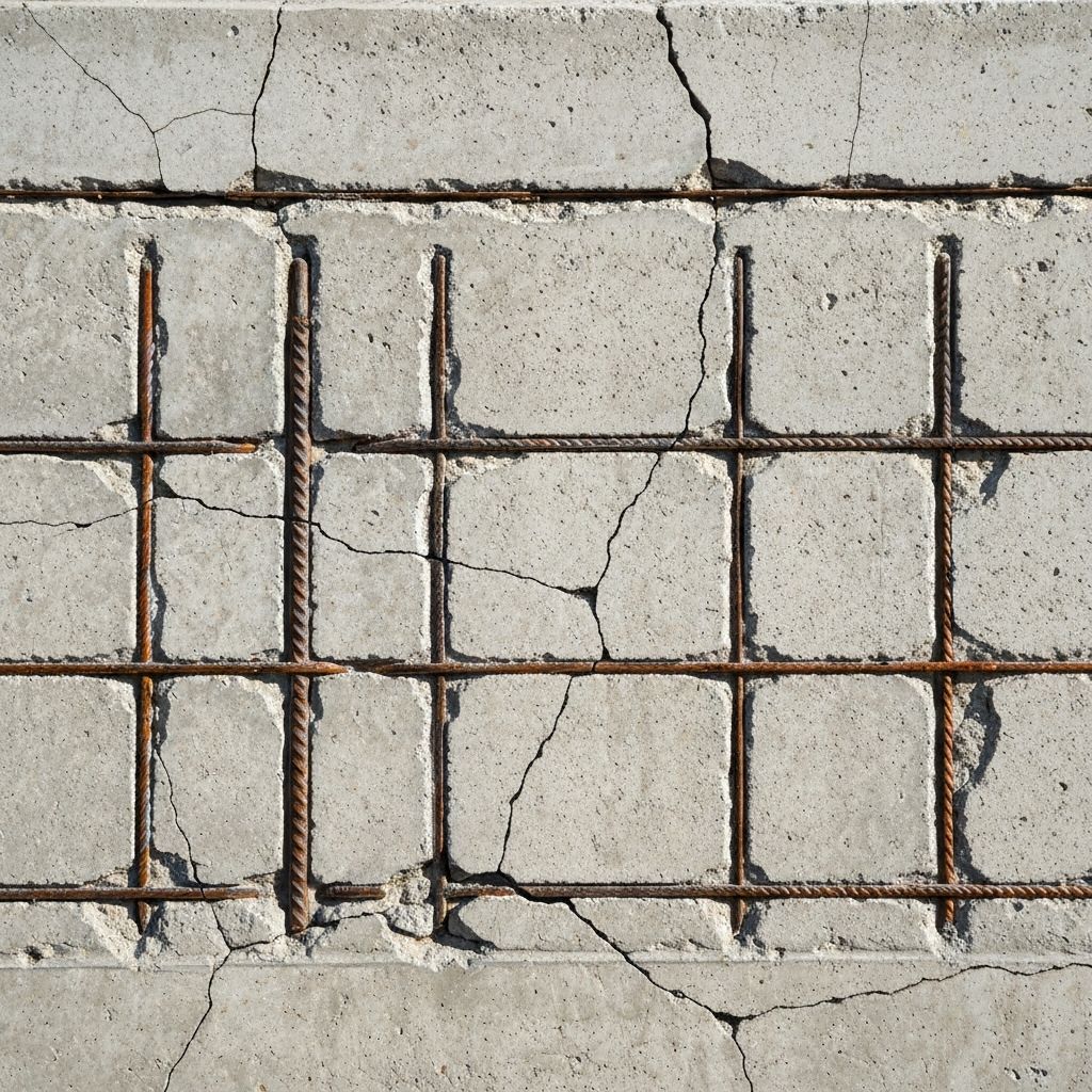
For slabs with two-way reinforcement, minimum applies in each direction, producing grid pattern. For walls subject to bending and axial force, minimum depends on which stress component dominates.
Quality assurance must verify that minimum reinforcement is provided for the actual loading case—common construction errors include:
- •Placing only one-way reinforcement when two-way required
- •Reducing reinforcement near supports where shear governs but tension reinforcement still required
- •Omitting reinforcement in compression zone when design shows compression-side reinforcement prevents tension cracking
Value engineering optimization should ensure reinforcement sizes and spacing are efficient within minimum area requirements, considering bar availability (typically 8, 10, 12, 16, 20, 25, 32 mm diameters), standard spacings (100, 150, 200, 250, 300 mm), and construction convenience.
Reinforcement Detailing Requirements and Construction Quality Control
EN 1992-1-1 Section 9 establishes detailing requirements ensuring minimum reinforcement functions effectively:
• Bond requirements—reinforcement must be deformed bars or otherwise developed for adequate bond; smooth bars or unbonded strands do not satisfy minimum reinforcement requirement
- •Concrete cover—minimum cover per Section 4.4 ensures bond development and protection
- •Anchorage—reinforcement must be properly anchored at ends and at connections
- •Continuity—where possible, bars should extend through potential crack locations rather than terminating short
- •Splicing—reinforcement splices must be properly located, overlapped, and documented
Construction quality control verifies:
• Bar types match design (deformed grade 500 per EN 1992, not smooth bars)
- •Bar sizes and spacings meet specifications within tolerances (±50 mm spacing tolerance typical)
- •Concrete cover meets requirements (±10 mm tolerance at construction phase)
- •Reinforcement is adequately supported to prevent movement during concrete placement
Quality assurance documentation includes:
• Shop drawings showing reinforcement layout and details
- •Material certificates confirming bar grade and properties
- •Construction photographs and inspection reports documenting reinforcement placement
- •As-built drawings updated with actual placement
Third-party inspectors typically perform random bar placement verification and concrete cover measurement using cover meters before concrete placement.
Effective Tension Stiffening and Bond-Dependent Crack Characteristics
The effectiveness of minimum reinforcement depends on tension stiffening—the reinforcement's ability to transfer stress through bond to surrounding concrete. EN 1992-1-1 Section 7.4 implicitly recognizes tension stiffening by requiring bonded reinforcement for minimum reinforcement to be effective. Key factors affecting tension stiffening and crack width:
• Bar diameter—smaller bars provide larger surface area for bond per unit volume, developing stiffness at lower stress concentration; however, practical minimum bar sizes are ~8 mm
- •Bar spacing—closer spacing (≤150 mm) provides more efficient crack distribution than wider spacing (>250 mm)
- •Concrete cover—adequate cover (≥25 mm for internal exposure) permits stress transfer before crack reaches surface
- •Concrete quality—higher strength and lower w/c ratio provide improved bond and reduced permeability
- •Bar surface deformation—standard deformed bars develop superior bond compared to smooth bars
Quality assurance must verify that bond conditions are adequate by checking:
• Concrete cover measured with cover meters • Concrete strength verified by compressive testing • Reinforcement surface condition inspected for rust, mill scale, or contamination
Any deviation from designed conditions (reduced cover, low concrete strength, corroded reinforcement) requires remedial action—possibly increasing reinforcement or redesigning section. Construction defects in bond conditions directly compromise the minimum reinforcement function, potentially leading to cracking failure despite nominal reinforcement being present.
Minimum Reinforcement in Restrained Sections and Composite Members
EN 1992-1-1 Section 9.2.1.2 addresses minimum reinforcement in sections subject to restrained shrinkage and temperature effects. When shrinkage or thermal deformation is restrained, tensile stress develops independently of bending loads. Minimum reinforcement for restrained sections is calculated as:
A_s,min = (A_c / f_yk) · max[f_ct,eff, (β_shrinkage · ε_cs + β_thermal · Δα · ΔT) · E_c]
where the stress calculation accounts for shrinkage strain (ε_cs), thermal strain (Δα · ΔT), and material properties. For typical conditions, minimum reinforcement for restraint ≈ 0.3-0.5% for slabs and walls.
Quality control procedures verify restraint analysis—determining whether element is fully restrained (fixed supports), partially restrained (friction at base), or unrestrained. For slabs on grade, friction restraint typically produces partial restraint increasing required minimum. For composite sections (such as beams with concrete topping), the effective area includes both members, but quality assurance must verify that topping reinforcement and beam reinforcement coordinate to provide complete coverage.
Construction quality control on composite members ensures both primary and secondary reinforcement are specified and installed correctly, with proper coordination between trades.
Value Engineering and Optimization Within Minimum Reinforcement Constraints
Value engineering optimization focuses on cost efficiency while maintaining or exceeding minimum reinforcement requirements—never compromising safety. Strategies include:
- •Bar size optimization—using fewer larger bars vs. more smaller bars to minimize labor (rebar splicing, tying) while maintaining area
- •Spacing efficiency—selecting spacings that balance reinforcement area, congestion, and constructability
- •Layout rationalization—using continuous bars through regions rather than lapped splices to reduce labor
- •Material selection—investigating high-strength reinforcement (yield 600 MPa) to reduce area when permitted, or considering supplementary materials (welded fabric) where appropriate and code-permitted
However, value engineering must never:
- •Reduce reinforcement area below calculated minimum
- •Use unbonded or smooth reinforcement when bonded deformed bars required
- •Compromise cover or anchorage to save material
- •Eliminate reinforcement in regions where minimum is mandatory
Quality assurance reviews all value engineering proposals to ensure no safety compromise—calculations must demonstrate revised design meets or exceeds minimum. Cost-benefit analysis must consider whole-life cost including durability and maintenance, not just initial construction cost. Structures with inadequate crack control reinforcement develop problems (excessive cracking, water infiltration, corrosion) leading to expensive remedial repairs—spending modest additional reinforcement cost initially is far more economical.
Design Documentation and Construction Inspection Procedures
Comprehensive documentation of minimum reinforcement requirements is essential for quality assurance in construction. Design drawings must clearly indicate:
- •Minimum reinforcement area required with calculation summary
- •Reinforcement layout showing bar sizes, spacing, and coverage
- •Cover requirements and specific dimensions from exposed surfaces
- •Anchorage details and lap splice specifications where required
- •Notes referencing calculation standards and code sections
Specifications should reference:
- •Reinforcement grade and source requirements
- •Placement tolerances (±50 mm spacing, ±10 mm cover typical)
- •Inspection and testing procedures
- •Remedial procedures for non-conforming installation
Construction inspection procedures include:
- •Pre-placement verification—shop drawing review, material certification review, bar placement inspection relative to formwork
- •During construction—spot checks of bar spacing and position, concrete cover measurement at 3+ locations per element
- •Post-placement—photographic documentation and final inspection before concrete placement
- •Post-construction—verification that as-built condition matches design (updated as-built drawings)
Non-conformance procedures address deficiencies:
- •Minor deviations (spacing ±25 mm, cover ±5 mm)—typically acceptable without remedial action
- •Significant deviations (spacing ±100 mm, cover ±25 mm)—require engineer evaluation and possible supplemental reinforcement
- •Major deviations (missing reinforcement, wrong bar grade)—require corrective action or section redesign
Quality assurance protocols ensure documentation is complete and construction compliance verified before structure acceptance.
Conclusion
EN 1992-1-1 minimum reinforcement requirements represent fundamental quality assurance protecting structures against brittle failure and ensuring adequate crack control. Proper calculation, design specification, construction detailing, and quality control verification are essential for achieving specified performance. VSG provides detailed minimum reinforcement calculations, design verification, construction inspection protocols, and quality assurance documentation per Eurocode 2 requirements. Contact our engineering team for design optimization, construction oversight, or remedial assessment of existing non-conforming reinforcement installations.
Related Testing Services
- Concrete Strength Testing
- Reinforcement Grade Verification
- Bar Placement Inspection
- Concrete Cover Measurement
- Bond Strength Testing
Applicable Standards
Professional Engineering Support
This testing and verification work is part of comprehensive construction management and quality assurance services provided by our architectural and engineering consulting team. We support project management, quality control, and commissioning across military, nuclear, infrastructure, and commercial sectors.
Request Engineering Services