EN 1992-1-1 (Eurocode 2: Design of Concrete Structures—Part 1-1) establishes comprehensive procedures for evaluating time-dependent deformations of concrete, specifically creep and shrinkage, which profoundly affect long-term structural behavior, deflection control, crack development, and prestress losses throughout the service life of reinforced and prestressed concrete structures. Creep—the phenomenon of continued deformation under sustained constant loading—and shrinkage—the volumetric change of concrete independent of applied loads—represent critical design considerations particularly for slender members, long-span structures, prestressed elements, and structures with sensitive serviceability criteria such as bridges, parking structures, and architectural facades. EN 1992-1-1 provides standardized methods for calculating creep coefficients and shrinkage strains based on concrete strength class, ambient humidity, concrete age at loading, element dimensions, and cement type, enabling engineers to predict cumulative time-dependent deformations and design appropriate preventive measures. Understanding creep and shrinkage mechanics, their interdependence with concrete composition and environmental conditions, and their interaction with structural response requires comprehensive knowledge of the Eurocode 2 provisions and their application to diverse structural typologies.
Creep Fundamentals and Physical Mechanisms
Creep represents the continued inelastic deformation of concrete under sustained constant compressive stress, distinct from elastic deformation that occurs instantaneously upon loading and shrinkage deformation that develops independent of applied loads. EN 1992-1-1 Section 3.1.4 establishes that creep depends on ambient humidity (decreasing with increasing humidity due to internal pore moisture interaction), concrete element dimensions (particularly the notional size h₀ = 2Ac/u reflecting exposure perimeter), concrete composition including cement type and strength class, concrete maturity when loading is first applied (creep increases significantly for early loading), and magnitude and duration of sustained loading. Physical mechanisms underlying creep involve moisture-dependent viscous flow of the cement paste matrix at microscopic scale, stress-induced microcracking and rearrangement of solid phases within the hydrated cement structure, and moisture transport-driven changes in capillary and gel pore pressures. The creep coefficient φ(∞,t₀)—defined as the ratio of creep deformation to elastic deformation—increases with time following logarithmic development over years or decades, with approximately 10% of ultimate creep occurring within the first day, 50% within the first month, and 75% within the first year under typical indoor conditions. Early-age loading produces greater total creep because more creep development remains possible over the remaining service life.
Creep Coefficient Determination per EN 1992-1-1
EN 1992-1-1 provides Figure 3.1 for determining creep coefficient φ(∞,t₀) under normal environmental conditions (ambient temperatures -40°C to +40°C, relative humidity RH 40-100%) as a function of concrete strength class (C20/25 through C90/105), concrete age at loading t₀ (from 1 day to >100 days), and notional member size h₀ in mm. The graphical method provides values for two standard conditions: inside conditions with RH = 50% and outside conditions with RH = 80%. Concrete strength class influences creep significantly; lower-strength concretes exhibit higher creep coefficients (approximately 5.0-7.0 for C20/25 at h₀ = 500 mm, RH = 50%) while high-strength concretes show reduced creep (approximately 1.8-2.3 for C80/95 under identical conditions) because stronger concretes have denser microstructure with reduced porosity. Age at loading dramatically affects creep; loading at early ages (t₀ = 1 day) produces creep approximately 2-3 times greater than loading at t₀ = 28 days because continued hydration and strength gain during the creep period reduces ongoing plastic deformation potential. The notional size h₀, calculated as 2Ac/u (twice the cross-sectional area divided by exposed perimeter), reflects member dimension effects; larger sections produce less creep per unit stress because internal regions dry more slowly, reducing drying-induced creep mechanisms. For sections with h₀ > 500 mm, creep coefficients are typically reduced by 10-30% compared to h₀ = 500 mm reference cases.
Non-Linear Creep and High Stress Conditions
When applied compressive stress exceeds 0.45 f_ck(t₀) (45% of characteristic concrete strength at loading age), creep becomes non-linear and the standard linear relationship between creep strain and stress no longer applies. Such elevated stresses commonly occur in prestressed concrete members at tendon level, heavily loaded columns with high sustained loads, or situations involving load redistribution in early-age concrete. EN 1992-1-1 Section 3.1.4(4) provides the non-linear notional creep coefficient: φ_nl(∞,t₀) = φ(∞,t₀) × [1 + 1.5(k_G - 0.45)/(1 - 0.45)] where k_G is the stress-strength ratio σ_c/f_ck(t₀). This expression demonstrates that creep amplification increases nonlinearly with stress level; at σ_c = 0.50 f_ck(t₀), creep coefficient increases by factor of 2.5; at σ_c = 0.60 f_ck(t₀), amplification increases to approximately 15 times baseline creep. The formula applies for stress ratios 0.45 ≤ k_G ≤ 1.0; stresses exceeding f_ck(t₀) cause material failure rather than additional creep. Non-linear creep significantly amplifies prestress losses in post-tensioned cables and dramatically increases deflections in prestressed members, necessitating careful prestress level control during design and construction phases.
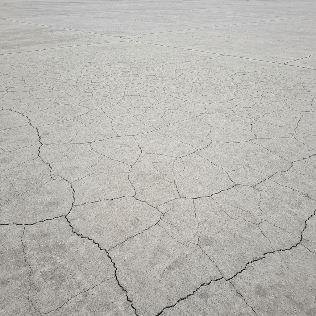
Total Shrinkage Strain Composition and Development
EN 1992-1-1 Section 3.1.4(6) establishes that total shrinkage strain ε_cs comprises two distinct components: drying shrinkage strain ε_cd and autogenous shrinkage strain ε_ca. Drying shrinkage results from moisture loss from concrete surface and internal transport through pores toward exposed surfaces, producing net volume reduction proportional to depth of moisture penetration and environmental relative humidity. Drying shrinkage develops slowly over months or years because moisture migration rate depends on concrete permeability and pore structure; the major portion typically develops over 3-5 years with development essentially complete after 10-20 years. Autogenous shrinkage represents volume change during cement hydration occurring independent of external moisture loss, resulting from the hydration reaction producing hydrates with lower molar volume than original reactants. Autogenous shrinkage develops rapidly during first days and weeks after casting, with approximately 75% completing within 2-3 weeks and essentially all development concluded within 1-2 years. For normal strength concretes (C20/25 to C50/60), autogenous shrinkage typically contributes 10-20% of total long-term shrinkage; for high-strength concretes (C80/95 to C90/105), autogenous contribution increases to 30-50% because high cement content produces greater hydration-driven volume changes.
Drying Shrinkage Calculation and Time-Dependent Development
EN 1992-1-1 provides Table 3.2 with nominal unrestrained drying shrinkage values ε_cd,0 (in ‰) for concrete with CEM cement Class N (ordinary Portland cement), differentiated by strength class and relative humidity. For example, C40/50 concrete at RH = 60% exhibits ε_cd,0 = 0.38 ‰, while C80/95 concrete under identical conditions exhibits ε_cd,0 = 0.24 ‰. Drying shrinkage decreases significantly with increasing concrete strength because higher strength implies lower porosity and reduced water capacity. Similarly, drying shrinkage decreases substantially with increasing ambient humidity; at RH = 100%, drying shrinkage becomes negligible (effectively zero) because concrete remains saturated and moisture migration ceases. The actual drying shrinkage strain at time t is calculated as: ε_cd(t) = β_ds(t,t_s) · k_h · ε_cd,0 where β_ds(t,t_s) is the time-dependent development function, k_h is a size reduction coefficient from Table 3.3 (ranging from 1.0 for h₀ = 100 mm to 0.70 for h₀ ≥ 500 mm), and ε_cd,0 is the nominal unrestrained value. The development function β_ds(t,t_s) = (t - t_s)³/[(t - t_s)³ + 0.04·h₀³] incorporates both time elapsed (t - t_s) and member notional size h₀, showing that shrinkage development is slower for larger members due to gradual interior moisture redistribution.
Autogenous Shrinkage Strain Formulation and Impact on High-Strength Concrete
EN 1992-1-1 provides explicit formulas for calculating autogenous shrinkage strain: ε_ca(∞) = 2.5(f_ck - 10) × 10⁻⁶ and ε_ca(t) = β_as(t) · ε_ca(∞) where β_as(t) = 1 - exp(-0.2 · t⁰·⁵) with t in days. For C20/25 concrete, autogenous shrinkage = 2.5 × (20 - 10) × 10⁻⁶ = 0.025 ‰; for C60/75, ε_ca(∞) = 2.5 × (60 - 10) × 10⁻⁶ = 0.125 ‰; for C90/105, ε_ca(∞) = 2.5 × (90 - 10) × 10⁻⁶ = 0.20 ‰. The development function β_as(t) shows rapid initial development; at t = 1 day, approximately 45% of ultimate autogenous shrinkage has developed; at t = 7 days, approximately 78% has developed; at t = 28 days, 90% of ultimate autogenous shrinkage has essentially completed. Autogenous shrinkage becomes particularly important in high-strength concrete used in prestressed members, causing unintended prestress increases (beneficial) but also contributing to early-age cracking if concrete is externally restrained. In unrestrained high-strength concrete elements, total shrinkage can exceed 0.50 ‰ (500 × 10⁻⁶ strain), producing substantial volumetric changes and requiring careful consideration in structural detailing.
Effects of Cement Type and Concrete Composition on Creep and Shrinkage
EN 1992-1-1 acknowledges that concrete composition significantly influences creep and shrinkage development but primarily through effects on strength class and cement characteristics rather than explicit formulas. Cements with rapid early strength gain (high C₃S and C₃A content, typical of normal Portland cement CEM I) produce higher early-age strength and reduced early creep but may produce higher ultimate creep. Cements with lower heat of hydration (such as composite cements CEM II or CEM III with fly ash, blast furnace slag, or pozzolan) develop strength more slowly, producing higher early-age creep (for same cement content and strength class) but potentially lower ultimate creep due to microstructural refinement from supplementary cementitious materials. Addition of supplementary cementitious materials (fly ash, slag, pozzolan) generally reduces both drying shrinkage and autogenous shrinkage relative to plain Portland cement concrete of equivalent strength, due to refined pore structure and reduced capillary pressure development. Water-cement ratio profoundly affects creep and shrinkage; lower w/c ratios produce higher strength, lower porosity, and reduced total creep and shrinkage development. Aggregate properties, particularly aggregate modulus of elasticity and moisture movement characteristics, influence apparent creep (stress-induced plus moisture-driven components) and drying shrinkage potential.
Prestress Loss Analysis: Immediate and Time-Dependent Components
EN 1992-1-1 Section 5.10 addresses prestress losses, with time-dependent losses (Section 5.10.6) directly caused by creep and shrinkage of concrete. Immediate losses occurring during and immediately after tensioning include losses due to instantaneous elastic deformation of concrete, friction in post-tensioning ducts, and anchorage slip at tensioning anchorages. Time-dependent losses develop progressively over weeks, months, and years and include losses from relaxation of high-strength prestressing steel (decreasing at sustained stresses below 0.55 f_py), creep-induced shortening of concrete transferring stress to prestressing tendons, and shrinkage-induced stress changes in statically determinate and indeterminate systems. The incremental loss of prestress force ΔP_c+s due to creep and shrinkage is calculated as: ΔP_c+s = A_p · E_p · Δε_cs = A_p · E_p · [φ(∞,t₀)·σ_c,qp(t₀)/E_c,eff + ε_cs(t)] where A_p is prestressing steel area, E_p is steel modulus, φ(∞,t₀) is creep coefficient, σ_c,qp is initial compressive stress in concrete due to prestress, E_c,eff is effective concrete modulus (typically 1.05 E_cm), and ε_cs(t) is total shrinkage strain. For typical post-tensioned concrete beams, time-dependent losses commonly range from 15-30% of initial prestress force, with creep contributing 8-15% and shrinkage contributing 7-15%, depending on concrete strength, curing conditions, and ambient humidity.
Long-Term Deflection and Crack Width Predictions
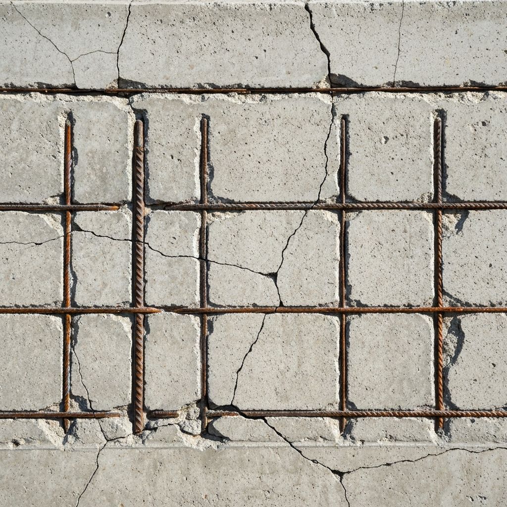
Time-dependent creep and shrinkage significantly amplify deflections beyond those predicted from elastic analysis alone, particularly in flexural members and slender elements. EN 1992-1-1 Section 7.4 (Deflection control) recognizes that long-term deflections result from combinations of immediate elastic deflection, sustained-load creep-induced deflection, and shrinkage-induced deflection. For simply-supported beams under uniform sustained load, creep-induced deflection commonly equals or exceeds elastic deflection, producing total long-term deflections approximately 2-3 times elastic deflections under normal ambient conditions (RH = 60-80%). Architectural cladding and finishes can be damaged or functional failures such as water entrapment can occur if deflection limits (typically L/250 to L/500 depending on application) are exceeded. Crack width development at serviceability limit states depends partly on creep and shrinkage; sustained tensile stress (from loading or restrained shrinkage) plus creep of concrete increases opening displacement of existing cracks. Differential shrinkage between restrained and unrestrained concrete (such as around columns) can produce significant tensile stresses and cracking if reinforcement is insufficient, requiring consideration of autogenous and drying shrinkage when detailing connections and construction joints.
Environmental Factors: Humidity, Temperature, and Curing Conditions
Ambient relative humidity exerts the dominant environmental influence on both creep and shrinkage. At RH = 100% (saturated conditions), drying shrinkage becomes negligible and creep reduces to basic creep (caused by loading alone); at RH = 50% (indoor conditions), drying shrinkage and total creep increase substantially compared to high-humidity conditions; at RH = 20% (very dry climates), drying shrinkage and creep reach maximum practical values. EN 1992-1-1 Figure 3.1 provides creep coefficients for RH = 50% and RH = 80% as reference conditions; for other humidity levels, interpolation between these values provides reasonable estimates. Temperature influences creep and shrinkage through multiple mechanisms: at elevated temperatures, creep rate increases due to accelerated moisture movement and increased viscous flow; at low temperatures below freezing, moisture is immobilized and creep essentially ceases though ice formation can cause damage. Curing conditions dramatically affect early-age creep and shrinkage; sealed or steam-cured concrete (preventing surface moisture loss during initial hydration) develops autogenous shrinkage but minimal drying shrinkage; air-cured concrete exposed to dry environment develops both autogenous and drying shrinkage simultaneously. Time of start of drying shrinkage t_s (typically end of curing period) significantly affects shrinkage development timing; extended curing periods delay start of drying shrinkage, distributing moisture-driven deformations over longer periods and reducing early-age cracking potential.
Design Considerations and Mitigation of Creep and Shrinkage Effects
Understanding creep and shrinkage is essential for successful long-term structural performance. Key design considerations include: (1) Member sizing and reinforcement to limit stresses and control crack widths under long-term combined loading and shrinkage; (2) Joint detailing and construction sequencing to accommodate anticipated shrinkage and differential movements between elements; (3) Prestress level optimization to maintain adequate prestress after time-dependent losses; (4) Deflection control by limiting service-load stresses, increasing member stiffness (larger dimensions, higher-strength concrete), or incorporating controlled prestress; (5) Crack control reinforcement in areas subject to restrained shrinkage such as connections and transitions. Mitigation strategies include reducing concrete permeability to slow drying shrinkage (lower water-cement ratio, higher-quality concrete), using low-shrinkage cements or supplementary materials, minimizing early-age loading to reduce early creep, maintaining favorable humidity conditions during and after construction, and providing adequate curing to complete early hydration before drying begins. For prestressed structures, accurate prediction of time-dependent losses ensures adequate long-term prestress retention and prevents overstress or stress reversal in extreme tendon zones.
Conclusion
EN 1992-1-1 provides comprehensive procedures for predicting concrete creep and shrinkage over the service life of reinforced and prestressed concrete structures. Proper understanding and application of creep coefficient determination, shrinkage strain calculations, and time-dependent deformation analysis are essential for achieving satisfactory long-term structural performance and serviceability. VSG provides expert consultation on creep and shrinkage analysis, long-term deflection predictions, prestress loss calculations, and time-dependent structural assessment per Eurocode 2 requirements. Contact our engineering team for detailed creep and shrinkage analysis, structural behavior prediction, and long-term performance verification for your concrete structures.
Related Testing Services
- Concrete Strength Testing
- Modulus of Elasticity Determination
- Creep Strain Measurement
- Shrinkage Strain Measurement
- Relative Humidity Monitoring
- Long-Term Deflection Monitoring
- Prestress Force Loss Measurement
Applicable Standards
Professional Engineering Support
This testing and verification work is part of comprehensive construction management and quality assurance services provided by our architectural and engineering consulting team. We support project management, quality control, and commissioning across military, nuclear, infrastructure, and commercial sectors.
Request Engineering Services