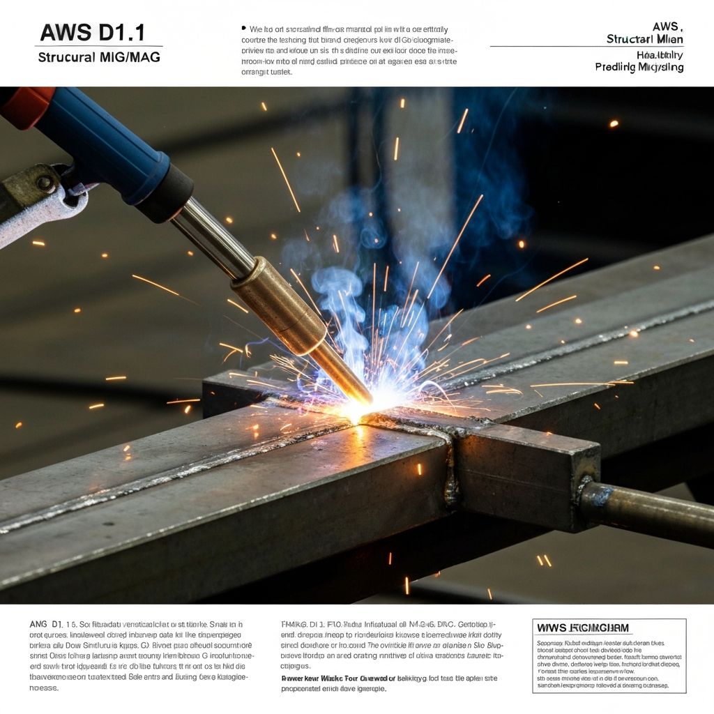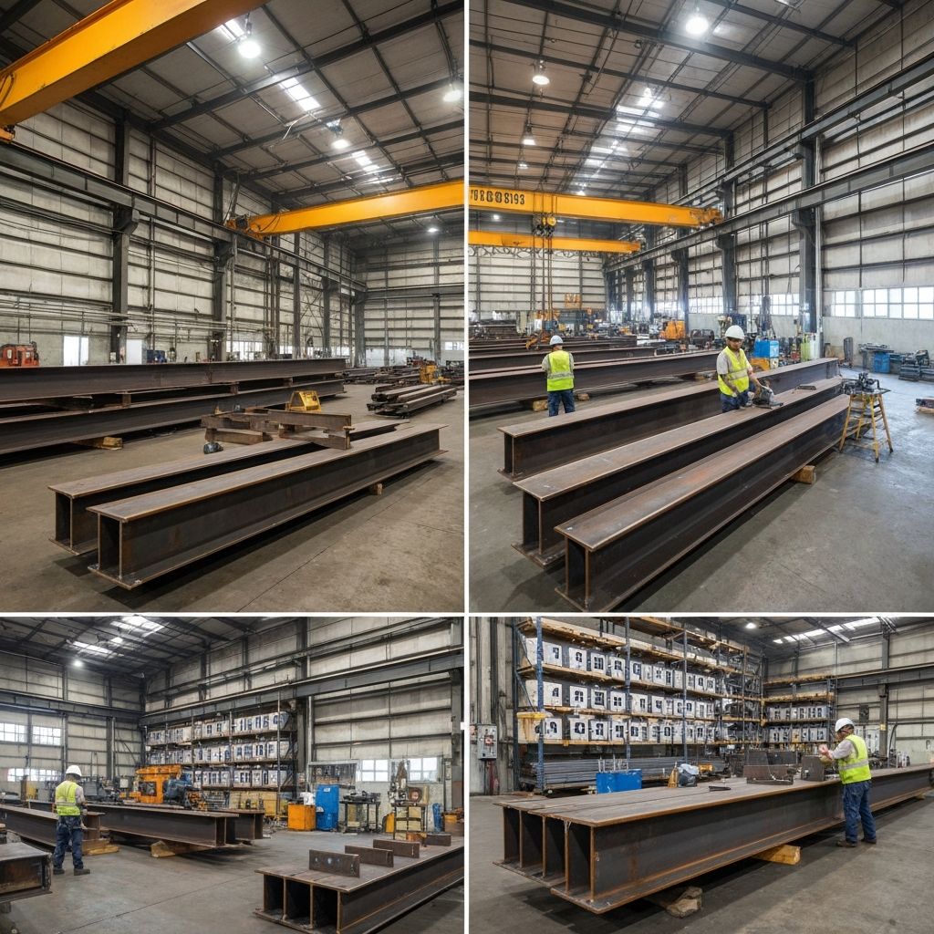
AWS D1.4/D1.4M is the American Welding Society specification for structural steel welding covering bridge and building construction. Quality control is paramount in structural welding—inadequate welds can compromise structural integrity, cause catastrophic failure, and result in loss of life. AWS D1.4 establishes rigorous requirements for welder qualification, welding processes, inspection procedures, non-destructive testing (NDT), acceptance criteria, and documentation to ensure all structural welds meet design requirements. This comprehensive guide addresses AWS D1.4 quality control procedures including visual inspection, ultrasonic testing, radiography, acceptance criteria, rejection and repair procedures, and documentation requirements essential for compliance and structural safety.
Welder and Welding Operator Qualification Requirements
AWS D1.4 requires all personnel performing structural welds to be qualified according to AWS D1.1 (Standard for Welding in the Structural, Pressure Vessel and for Bridges and Building Construction). Welder qualification is a fundamental requirement ensuring that each welder demonstrates competence to produce welds meeting design and quality requirements. Qualification involves demonstrating competence through test coupons—samples of welding executed under controlled conditions and tested to verify compliance with mechanical property requirements including tensile strength, yield strength, elongation, and impact resistance (for critical applications). Initial qualification requires successful test welds in the applicable positions (1G/PA for flat position, 2G/PC for horizontal, 3G/PF for vertical, 4G/PF for overhead; pipe positions 1G/2G/5G/6G) and thickness range (typically thin—under 3mm, medium—3 to 6mm, or thick—over 6mm). Qualification test coupons are typically 10-12 inches in length and matched to the anticipated production thickness and position. Qualification testing includes tensile tests of welded coupons (measuring ultimate tensile strength and elongation to verify meeting minimum requirements), bend tests of heat-affected zones (requiring the coupon to bend without cracking), and visual inspection verification of weld profile and surface condition. The welder must successfully pass all mechanical tests and visual inspection; failure of any test requires re-qualification. Qualification is valid for 6 months from the date of qualification test provided the welder remains actively engaged in structural welding (working in the process at least once per 6-month period); if a gap exceeds 6 months without work in that process, requalification is required before resuming production welding. Welding operators (for semi-automatic or automatic processes) must similarly demonstrate competence; automated welding processes require procedure qualification per ASME and AWS standards plus operator training and evaluation. Different welding processes (SMAW—stick, GMAW—MIG, FCAW—flux core, GTAW—TIG, SAW—submerged arc) require separate qualifications. Documentation of all welder qualifications including test coupon identification, test date, test results (tensile data, bend test results), identification numbers, and expiration dates must be maintained and available at the jobsite for inspection and audit. Expired qualifications or qualifications in different welding processes require requalification before resuming structural work.
- AWS D1.1 qualification: All structural welders must be qualified per AWS D1.1 standards
- Initial qualification: Successful test coupons in applicable positions (1G, 2G, 3G, 4G) and thickness range
- Coupon thickness: Thin (≤3mm), medium (3-6mm), or thick (>6mm) determines qualification coverage
- Test procedures: Tensile tests (ultimate strength, elongation), bend tests (no cracking), visual inspection
- Mechanical requirements: Minimum tensile strength per material specification; elongation minimums verified
- Impact testing: Charpy V-notch impact tests may be required for critical applications or low-temperature service
- Validity period: 6 months from qualification date; requalification if gap exceeds 6 months of non-work
- Active engagement requirement: Welder must work in the qualified process at least once per 6-month period
- Process-specific qualification: SMAW, GMAW, FCAW, GTAW, SAW each require separate qualification
- Position and thickness coverage: Qualification in 3G/PF thick position typically covers most applications
- Requalification triggers: Expired qualification, gap exceeding 6 months, or poor weld quality
- Operators and procedures: Semi-automatic/automatic processes require operator training plus procedure qualification
- Documentation: Maintain qualification records with coupon ID, test dates, mechanical property results, expiration dates
- Jobsite availability: Records available for inspection verification before production work commences
Welding Procedure Specification (WPS) Development and Qualification
AWS D1.4 requires a qualified Welding Procedure Specification (WPS) before production welding commences. WPS is a detailed written document that defines all parameters controlling weld quality and process repeatability. WPS parameters include: base material specification (ASTM designation, grade, thickness), filler metal type (electrode classification per AWS A5 series—e.g., E7018 for SMAW, ER70S-2 for GMAW) and diameter/wire size, joint design geometry (groove angle, root opening, land distance for butt welds; leg size and angle for fillet welds), welding position (flat/horizontal/vertical/overhead), preheat temperature (minimum and maximum, often 50-150°C for structural steel), interpass temperature (maintained during multi-pass welding), heat input (calculated from current, voltage, and travel speed—typically 15,000-40,000 joules per inch for structural work), travel speed (inches per minute), shielding gas composition and flow rate (argon/CO2 mixtures, typically 15-25 CFM), backing requirements (if applicable), and cooling/PWHT (post-weld heat treatment) procedures. WPS development involves testing per ASME Section IX or AWS D1.1 to verify that the procedure produces acceptable welds meeting mechanical property requirements including minimum tensile strength (typically 70,000 psi for most structural steel), yield strength, elongation (minimum 17-20%), and impact properties if required. Procedure Qualification Records (PQRs) document the testing results of representative test coupons—tensile strength, yield strength, elongation percentage, and hardness values. Multiple PQRs may be required to cover the range of parameters expected in production: different thickness ranges (thin, medium, thick), material types (A36, A572, A588, A992), positions, and filler metal types. PQR testing typically includes three test coupons welded under controlled conditions and tested: tensile tests measure ultimate strength and ductility; transverse and longitudinal bend tests verify weld and HAZ ductility; hardness surveys across the weld identify brittle zones. Once qualified, only welders certified in that specific WPS are permitted to perform production welds using those parameters—unauthorized deviations are non-conformances. Changes to critical parameters (base material type or thickness range, filler metal type/size, position, preheat temperature, heat input range exceeding limits) require new WPS qualification or formal amendment with supporting test data and engineering approval. Minor parameter adjustments within defined ranges (e.g., 25-30 amps within a 20 amp band) do not require requalification if WPS defines the range.
- WPS mandatory: Qualified procedure specification required before any production welding begins
- Base material: Specification (ASTM), grade, thickness, and condition specified in WPS
- Filler metal: AWS classification, type, size/diameter, and composition defined per AWS A5 standards
- Joint geometry: Groove angle, root opening, land distance (butt) or leg size/angle (fillet) specified
- Welding position: 1G (flat), 2G (horizontal), 3G (vertical), 4G (overhead) defined per requirements
- Preheat temperature: Minimum and maximum preheat required before welding begins (typically 50-150°C)
- Interpass temperature: Maintained between passes to control cooling rate and properties
- Heat input control: Calculated from amperage, voltage, travel speed; critical for mechanical properties
- Shielding gas: Composition (argon/CO2 blend) and flow rate (15-25 CFM typical) specified
- Procedure Qualification Records: PQR test results document weld properties (tensile, hardness, bend tests)
- Tensile strength: Minimum typically 70,000 psi; must exceed base material minimum specified
- Elongation requirement: Minimum 17-20% elongation verifies ductility and fracture resistance
- Bend testing: Transverse and longitudinal bends verify weld and HAZ ductility without cracking
- Hardness surveys: Vickers hardness measured across weld to identify brittle zones or segregation
- Impact testing: Charpy V-notch impact may be required for low-temperature or critical applications
- Multi-thickness coverage: PQR in thick material typically qualifies thin and medium thicknesses
- Parameter coverage: Multiple PQRs for different material types, thicknesses, and filler metals
- Qualified welder requirement: Only certified welders may perform work under qualified WPS
- Parameter deviation: Critical changes require new WPS qualification and amendment
- Minor adjustments: Changes within defined parameter ranges don't require requalification
Visual Inspection and Surface Examination
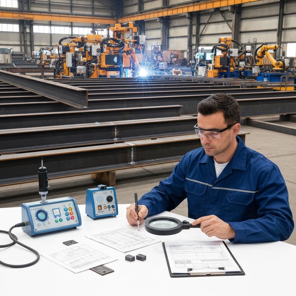
Visual inspection (VI) is the primary and most cost-effective quality control method for structural welds under AWS D1.4, performed by Certified Welding Inspectors (CWI) trained and certified per AWS QC1 standard. Visual inspection is the first-line defense against weld defects and is performed at multiple stages during fabrication. Visual inspection examines weld surface for discontinuities and defects including: incomplete fusion (lack of bonding between weld metal and base metal), lack of penetration (weld metal not extending through the joint thickness), undercut (groove in base metal at weld edge, reducing section), overlap (weld metal extending onto base metal outside the joint), spatter (metal droplets adhering to adjacent surface), cracks (surface breaking discontinuities from stress concentration or hydrogen embrittlement), porosity (gas pockets in weld metal), slag inclusions (non-metallic material trapped in weld), and dimensional compliance (actual weld size matches design dimensions). Visual inspection per AWS D1.4 requires inspection of 100% of all welds at several distinct stages: during welding (in-process inspection to identify problems before completion), after welding (final inspection prior to acceptance testing), and post-repair inspection (verification that repairs meet acceptance criteria). In-process visual inspection occurs as the welder is working, allowing real-time feedback and correction of technique issues. Final visual inspection occurs after the weld cools to room temperature, ensuring completed work meets surface criteria. Post-repair inspection verifies that corrective actions eliminated defects. Acceptance criteria for visual inspection are defined in AWS D1.4 tables and depend on joint type (butt or fillet welds), base material thickness, and design requirements. Superficial discontinuities (small undercut less than 1.6mm, minor spatter) may be acceptable provided they do not exceed acceptance criteria limits defined in the specification. Unacceptable defects (any cracks, lack of fusion exceeding defined limits, excessive undercut, porosity clusters) require rejection and repair. Visual inspection employs specialized tools: magnification (7x or 10x magnifying lens) for detailed surface examination, portable ultrasonic thickness gauges to verify weld profile and detect internal cavities, fillet weld gauges (concave, convex, depth gauges) for dimensional verification of fillet weld legs and profile, straight edges for checking surface contour, and lighting (minimum 50 foot-candles) for adequate visibility of weld surface. Surface preparation before inspection may include wire brushing or light grinding to remove spatter and discoloration, enabling accurate defect assessment. CWI inspectors maintain detailed records noting weld locations, dimensions, discontinuities observed, and acceptance/rejection decisions.
- Visual inspection: Primary QC method; 100% of all welds inspected at multiple stages
- Certified personnel: CWI (Certified Welding Inspectors) per AWS QC1 standard perform inspection
- In-process inspection: During welding to identify problems before completion; enables real-time feedback
- Final visual inspection: After cooling; assesses completed weld against acceptance criteria
- Post-repair inspection: After repair work to verify corrections eliminated defects
- Discontinuities examined: Cracks, lack of fusion, undercut, overlap, spatter, porosity, slag, dimensional issues
- Acceptance criteria: Defined per AWS D1.4 tables based on joint type and base material thickness
- Superficial defects: Undercut <1.6mm, minor spatter acceptable if dimensions meet requirements
- Rejectable defects: Any cracks, lack of fusion exceeding limits, porosity clusters
- Magnification: 7x or 10x magnifying lens for detailed weld surface examination
- Fillet weld gauges: Concave, convex, leg gauges for dimensional verification and profile assessment
- Thickness verification: Ultrasonic thickness gauges detect internal cavities and verify weld profile
- Lighting requirements: Minimum 50 foot-candles illumination for adequate visibility
- Surface preparation: Wire brush or light grind to remove spatter before final inspection
- Straightedge check: Verify weld surface contour and profile alignment
- Documentation: Record weld locations, dimensions, discontinuities, inspection method, acceptance decision
- Cold weather adjustments: Cold surfaces may reduce visual inspection accuracy; warming may be required
- Sectioning and examination: Cross-section samples may be removed for metallographic examination if defects unclear
Non-Destructive Testing (NDT) Methods: Ultrasonic, Radiography, and Other Techniques
AWS D1.4 permits several non-destructive testing methods to detect internal weld defects and discontinuities not visible on surface inspection. These methods complement visual inspection and provide confidence in internal weld quality. Ultrasonic Testing (UT) per ASTM E494 (automated) or ASTM E797 (manual) is the most common and practical method for structural welding, using high-frequency sound waves (typically 2-10 MHz frequency) to detect and locate discontinuities deep within the weld. UT operates by transmitting ultrasonic pulses into the weld through a transducer; the pulses reflect off defects or the back wall, with the reflected signals displayed on an A-scan (amplitude vs. time) display. UT is particularly sensitive to cracks, lack of fusion (discontinuities between weld and base metal), porosity (gas pockets), inclusions (slag or tungsten), and laminations. UT can be automated (immersion tank with scanning heads) or manual (hand-held probe with coupling gel applied to weld surface); manual UT is typical for large bridge and building structures where portability is essential. Ultrasonic testing advantage is rapid assessment without requiring material removal; disadvantages include surface roughness affecting signal transmission, angled defects potentially missing detection, and operator training/certification requirements. Radiography (X-ray per ASTM E94 or gamma ray per ASTM E1444) provides visual images of internal defects through photographic film or digital detection. X-ray exposes the weld to high-energy electromagnetic radiation; the radiation passes through the material with differential absorption based on density—defects (cracks, porosity, inclusions) appear as darker areas on the radiographic film. Film sensitivity and density are critical for defect detection. Radiography advantage is visual documentation of defects with clear spatial relationship; disadvantages include time requirements, radiation safety requirements, and cost. Magnetic Particle Testing (MPT) per ASTM E1316 detects surface and near-surface cracks in ferrous materials using magnetic fields to reveal discontinuities. A magnetic field is induced in the component, and ferromagnetic particles (iron powder) are applied; particles concentrate at defects revealing their location and orientation. MPT is particularly sensitive to hydrogen cracking in the heat-affected zone. Liquid Penetrant Testing (LPT) per ASTM E1417 detects surface cracks and is useful for non-ferrous materials (aluminum, stainless steel) where magnetic testing is ineffective. A penetrating liquid is applied to the weld surface, capillary action draws penetrant into surface-breaking cracks. After cleaning, a developer powder is applied, and concentrated penetrant is drawn back out of cracks, revealing defect location. Acceptance criteria for NDT are defined in AWS D1.4 Appendix A and depend on material thickness and joint type: for UT, allowable defect indications are quantified in terms of percentage of weld thickness equivalent (%WSE)—comparison of detected signal amplitude to calibration reference blocks; typical acceptance might be 15%WSE for linear indications and 25%WSE for isolated porosity. Radiographic acceptance per ASTM E446 defines maximum allowable defect sizes based on weld length: porosity clusters, slag inclusions, and tungsten inclusions must be within size limits; any cracks are typically rejectable. UT is often specified for critical welds (load-bearing connections, main structural members) due to speed and sensitivity; radiography is often used for smaller components or when visual documentation of defects is required for record-keeping and engineering evaluation. Advanced techniques including Phased Array UT (multiple element transducers enabling 2D scanning) and Time-of-Flight Diffraction (TOFD, 3D defect sizing) provide enhanced defect characterization. Combination testing (UT supplemented by radiography or MT) provides highest confidence in defect detection and characterization, particularly for critical structures.
- Ultrasonic Testing (UT): Primary NDT; detects internal discontinuities via sound wave reflection
- UT frequency: 2-10 MHz frequency pulses; reflected signals displayed on A-scan or C-scan
- Manual UT: Hand-held probes with coupling gel; portable for large structures
- Automated UT: Immersion tank with scanning heads for controlled laboratory testing
- UT sensitivity: Detects cracks, lack of fusion, porosity, inclusions, and laminations
- Acceptance criteria: AWS D1.4 defines allowable defects in %WSE (weld thickness equivalent)
- Linear defects: Typically 15%WSE maximum; isolated porosity 25%WSE tolerance
- Radiography (X-ray): Per ASTM E94; creates visual film image of internal defects
- Gamma ray radiography: Portable cobalt-60 or iridium-192 sources; slower than X-ray
- Film density: Proper film density (optical density 2.0-3.5) critical for defect detection
- Radiographic sensitivity: IQI (Image Quality Indicators) verify minimum detectable defect size
- Radiographic acceptance: ASTM E446 defines maximum allowable defect sizes by weld length
- Magnetic Particle Testing (MPT): Surface and near-surface crack detection in ferrous steel
- Hydrogen crack sensitivity: MPT particularly sensitive to heat-affected zone hydrogen cracking
- Liquid Penetrant Testing (LPT): Surface crack detection; effective for non-ferrous materials
- Capillary action: LPT uses penetrant draw-back to reveal surface-breaking discontinuities
- Material compatibility: LPT for aluminum, stainless steel; MPT for ferrous materials only
- Critical welds: UT often specified for load-bearing connections and main structural members
- Smaller components: Radiography often used for components or when documentation required
- Phased Array UT: Multi-element transducers; 2D scanning with enhanced defect characterization
- Time-of-Flight Diffraction: TOFD technique enables 3D defect sizing and accurate location
- Combination testing: UT + radiography or MPT provides highest defect detection confidence
- Third-party NDT: Independent certified technicians often perform critical weld testing
Acceptance Criteria and Defect Evaluation
AWS D1.4 defines specific, quantified acceptance criteria for structural welds based on visual inspection, radiography, and ultrasonic testing results. Acceptance criteria vary based on weld type (butt or fillet), joint configuration, base material thickness, and design classification. Visual inspection acceptance criteria for groove welds (butt joints) are defined in AWS D1.4 Table 4.7 and depend on thickness: maximum undercut depth typically limited to 1.6mm (1/16 inch) or 10% of the thinner material thickness—whichever is smaller. Cracks in any amount are not acceptable (zero tolerance). Longitudinal and transverse cracks result in automatic rejection. For fillet welds, acceptance criteria per AWS D1.4 Table 4.8 specify: surface cracks not acceptable (zero tolerance); undercut acceptable if not exceeding specified depth limits (typically 0.8-1.6mm depending on thickness); spatter and porosity acceptable if not exceeding size/count limits. Porosity acceptance criteria: isolated porosity acceptable if smaller than a specific diameter (typically 3mm); porosity clusters (multiple pores) not acceptable if exceeding specified diameters. Overlap (weld metal extending onto base metal) not acceptable in locations creating reentrant conditions. Radiographic acceptance criteria per ASTM E446 define maximum allowable defect sizes based on weld thickness and length: rounded porosity acceptable up to specific diameters (typically 2mm or 3% thickness, whichever is smaller) if isolated, but clusters exceeding limits are rejectable; slag inclusions acceptable if scattered and small, but linear slag or large clusters rejectable; tungsten inclusions (from GTAW process) small amounts acceptable; any crack or lack of fusion is typically rejectable regardless of size. Ultrasonic testing acceptance criteria per AWS D1.4 are quantified in terms of percentage of weld thickness equivalent (%WSE)—the detected signal amplitude is compared to calibration reference blocks where 100%WSE represents the signal from a known defect size. Typical acceptance criteria might specify: linear defects (cracks, lack of fusion) no indication exceeding 20%WSE or 1/4 thickness, whichever is greater; isolated rounded porosity acceptable if not exceeding 25%WSE; multiple indications requiring cumulative evaluation. Defects exceeding acceptance criteria are classified as rejectable and require repair or material removal and replacement. Minor surface defects (undercut 0.8mm or less, minor spatter in acceptable locations) may be acceptable even if they slightly exceed criterion limits if light grinding or other surface treatment is performed to restore dimensions, followed by re-inspection (visual and/or magnetic particle testing) to verify no subsurface defects exist. Evaluation of borderline or uncertain defects may require additional testing: radiographic confirmation of UT signals; magnetic particle testing of ground areas; sectioning and metallographic examination to determine acceptability; or consultation with the project engineer or designer. Engineering evaluation of defects must balance practical repair considerations against structural adequacy—over-acceptance risks performance issues, while excessive rejection creates schedule and cost impacts. Documentation of all defect evaluations, acceptance decisions, engineering approvals, and corrective actions provides the record justifying structural adequacy.
- Visual acceptance (groove): Max undercut 1.6mm or 10% thickness (whichever smaller)
- Visual acceptance (fillet): No cracks; undercut max 0.8-1.6mm; spatter acceptable per size
- Crack acceptance: Zero tolerance; any crack results in rejection regardless of size
- Porosity acceptance: Isolated ≤3mm acceptable; clusters exceeding limits rejected
- Overlap rejection: Reentrant overlap conditions not acceptable (creates stress concentration)
- Radiographic criteria: ASTM E446 defines maximum allowable defect sizes by thickness/length
- Rounded porosity: Isolated ≤2mm or 3% thickness acceptable; clusters rejected
- Slag inclusions: Scattered small amounts acceptable; linear slag or clusters rejected
- Tungsten inclusions: Small amounts acceptable in GTAW welds per limits
- Radiographic cracks: Any crack detection typically results in rejection
- UT acceptance criteria: AWS D1.4 defines allowable defects in %WSE (weld thickness equivalent)
- Linear defects: No indication exceeding 20%WSE or 1/4 thickness (whichever greater)
- Isolated porosity (UT): Acceptable if not exceeding 25%WSE; multiple indications cumulative
- Minor defects: Small undercut <0.8mm, spatter acceptable if cleaned and re-inspected
- Surface treatment: Grinding or finishing may restore acceptance if no subsurface defects
- Borderline evaluation: Additional testing (radiography, MT, metallography) for uncertain defects
- Sectioning: Cross-section samples removed for metallographic examination if defects unclear
- Engineering consultation: Uncertain defects require design engineer evaluation and approval
- Repair requirements: Rejectable defects require removal and reweld or alternative remediation
- Documentation: Defect records with location, size, evaluation method, acceptance decision, signatures
- Design vs. inspection: Defect acceptance limited by thinner of design specification or inspection standard
Defect Rejection, Repair Procedures, and Re-inspection
AWS D1.4 requires that any weld exceeding acceptance criteria be rejected for service and undergo repair or removal and replacement. Rejected welds are not permitted in the final structure unless engineering evaluation and approval document an alternative resolution. Repair of rejected welds must be performed by the same qualified welder or a welder with demonstrated competence and qualifications in the repair process; the repair weld must meet all original design requirements and acceptance criteria. Multiple repair attempts on the same location may be prohibited—some specifications limit repairs to one attempt, with removal and replacement required if the repair fails inspection. Repair methods vary depending on defect type and severity: for internal defects (cracks, lack of fusion, porosity), removal and replacement (gouging out the defective weld and rewelding) is most common and most reliable. Gouging removes the defective material plus a controlled amount of surrounding sound metal (typically 6mm minimum beyond defect), establishing clean metal for rewelding. Gouging methods include air carbon arc gouging (most common), plasma cutting, or mechanical grinding depending on location and material thickness. After gouging, the cleaned area is inspected to verify complete defect removal. The repair weld follows the same Welding Procedure Specification (WPS) or an approved repair procedure (sometimes slightly modified to account for geometry changes from gouging); the repair weld is subjected to the same inspection rigor as original production welds—visual inspection, NDT if required, mechanical testing if applicable. For minor surface defects (small undercut, spatter, cold lap on surface), repair may consist of grinding or other surface finishing to restore dimensions and remove stress concentrations, followed by surface examination (visual inspection, magnetic particle testing, or liquid penetrant testing to depth-assess the defect) to verify no subsurface cracks or discontinuities exist. Grinding removes surface material; depth of grinding must be controlled to avoid removing excessive material or grinding through surface protective coatings. Re-inspection of repaired welds is mandatory and non-negotiable—all repairs are subjected to the same or more rigorous inspection as original production welds (100% visual inspection, plus NDT if original inspection included NDT). Repair inspection documentation must show that the repaired weld now meets acceptance criteria. If a repair weld subsequently fails inspection (detected defect in the repair), escalation to engineering is required to determine if additional investigation, testing, or redesign is necessary. Some specifications permit limited repeat repairs (typically one); others require removal and redesign if a repair fails. Cascading failure (repair weld failure) indicates potential process or material issues requiring investigation. Documentation of all rejections, repair procedures, repair method (gouging, grinding, etc.), repair WPS or procedure used, re-inspection results, and any engineering approvals must be maintained and available for project records, audits, and future liability investigations.
- Rejection requirement: Any weld exceeding acceptance criteria must be rejected and repaired
- Service prohibition: Rejected welds not permitted in final structure without engineering approval
- Qualified repairers: Same or qualified welder with demonstrated competence must perform repair
- Repair competence: Welder must have proven success repairing similar defects
- Design compliance: Repair weld must meet all original design strength requirements
- Repair limitations: Some specs limit repairs to one attempt; removal/replacement if repair fails
- Removal and replacement: Gouging removes defect + 6mm surrounding sound metal minimum
- Gouging method: Air carbon arc, plasma cutting, or mechanical grinding per location
- Cleaned surface inspection: Post-gouge verification that defect completely removed
- Repair WPS compliance: Repair uses original WPS or approved alternative procedure
- Repair inspection: Same rigor as original—100% visual + NDT if specified
- Minor surface repair: Grinding to remove small undercut/spatter + surface examination
- Grinding depth control: Controlled material removal; avoid coating penetration
- Surface examination: Visual, MPT, or LPT to verify no subsurface defects post-grinding
- Re-inspection documentation: Repair passes acceptance criteria; records maintained
- Failed repairs: Cascading failures escalated to engineering; investigation required
- Repeat repairs: Limited attempts typically permitted; removal/replacement if fails
- Cascading investigation: Process/material issues identified if repeat repairs required
- Documentation: Rejection notices, repair procedure, method, WPS, re-inspection results, approvals
- Audit trail: Complete record maintained for project verification and liability defense
Inspection Personnel Certification and Qualifications
AWS D1.4 requires that structural weld inspection be performed by trained, certified personnel with demonstrated competence and knowledge of welding processes, AWS standards, and quality control requirements. Certified Welding Inspectors (CWI) are the standard requirement for structural welding inspection. CWI certification is issued by the American Welding Society and requires individuals to demonstrate knowledge through written and practical examinations covering welding processes, inspection methods, AWS standards (D1.4, D1.1, etc.), metallurgy, materials, inspection techniques, and quality control procedures. CWI certification requires passing a comprehensive written exam (minimum score 70%), a practical inspection exam (minimum score 70%), and an open-book proctored exam demonstrating knowledge of AWS codes. CWI certification is valid for 3 years; continuing education (CEU credits—minimum 15 CEUs per 3-year period) is required for renewal. CWIs must maintain current knowledge of AWS standards and attend continuing education courses in welding inspection, welding metallurgy, NDT methods, and relevant codes. Visual inspection may alternatively be performed by Visual Inspectors (VI) with documented training specific to the project including welding codes, acceptance criteria, project specifications, and company procedures. VIs need not have formal AWS certification but must demonstrate competence through on-the-job training and documented assessment. VI training must be provided by the contractor or fabricator and documented with dates and topics covered. Radiographic film interpreters must be certified per ASNT SNT-TC-1A (or ISO 4871) at Level II or III for radiography interpretation. Level II certification requires demonstrated knowledge of radiographic principles, film interpretation, and code compliance. Level III certification (above Level II) permits examination system qualification, procedure development, and training of lower-level technicians. Ultrasonic testing technicians performing UT inspection should be certified per ASNT SNT-TC-1A Level II or III in ultrasonic inspection. Level II UT certification requires knowledge of ultrasonic principles, equipment operation, test procedures, and defect evaluation. All NDT personnel (UT, RT, MPT, LPT) should maintain current certifications and training records, including identification numbers and expiration dates. Inspectors performing weld inspection must be independent of the fabricator and contractor to ensure unbiased, objective evaluation—an inspector employed by the fabricator may have conflicts of interest. For critical structures or owner requirements, third-party (consulting engineer or independent inspection agency) inspection is often specified to verify project compliance and provide independent verification of structural quality. Independent inspectors provide greater assurance that inspection is performed rigorously without pressure to overlook marginal defects. Documentation of all inspector qualifications (CWI card numbers and expiration dates, ASNT certifications with levels and expiration dates, training records) must be maintained and verified before inspection work commences. Inspectors must provide current certificates and identification proving valid certifications. Expired certifications or qualifications in different welding processes require requalification or new certifications before performing inspection work. VSG and other consulting firms provide qualified independent inspection services employing CWI-certified welding inspectors with extensive structural welding experience.
- Certified Welding Inspectors (CWI): AWS QC1 certification required; written and practical exams
- CWI exam requirements: Written exam (70% minimum), practical exam (70% minimum), open-book proctored
- CWI validity: 3 years from certification date; CEU renewal credits required for continuation
- Continuing education: Minimum 15 CEUs per 3-year period for CWI certification renewal
- CWI knowledge: Welding processes, inspection methods, AWS codes, metallurgy, materials, QC
- Visual Inspectors (VI): Documented training required; project-specific training and competence assessment
- VI qualification: On-the-job training provided by contractor; documented with dates/topics
- Radiographic interpreters: ASNT Level II or III certification required for film interpretation
- Radiography certification: Knowledge of principles, film interpretation, and code compliance
- UT technicians: ASNT Level II or III certification in ultrasonic inspection recommended
- UT certification: Knowledge of principles, equipment, procedures, and defect evaluation
- Other NDT: MPT and LPT personnel should maintain ASNT certifications per project requirements
- Inspector independence: Independent of fabricator/contractor to ensure unbiased evaluation
- Third-party inspection: Consulting engineer or independent agency for critical structures
- Inspection objectivity: Independent inspection reduces pressure to overlook marginal defects
- Certification documentation: Maintain CWI cards, ASNT certs, expiration dates, training records
- Jobsite verification: Verify current certifications before inspection work begins
- Expired certifications: Requalification required before performing inspection if expired
- Identification numbers: CWI numbers and ASNT credentials maintained for audit/verification
- Consulting inspection: Third-party firms provide independent verification of structural quality
Documentation, Records, and Traceability
AWS D1.4 requires comprehensive documentation of all welding and inspection activities to provide evidence of compliance with the standard and enable investigation of any future performance issues. Complete documentation creates an audit trail and demonstrates that proper procedures were followed throughout fabrication and construction. Documentation required includes: Welding Procedure Specifications (WPS)—detailed written procedures defining all parameters controlling production welding for each joint type and material combination; and Procedure Qualification Records (PQRs)—test results documenting that each WPS produces acceptable weld mechanical properties. Multiple PQRs may support a single WPS to demonstrate compliance across different thickness ranges or material types. Welder qualification records with test results showing tensile strength, yield strength, elongation percentage, bend test results (distances bent without cracking), and hardness values of qualification test coupons. Welder qualification records include test coupon identification, test date, expiration date, and welder identification number. Inspection and Test Plans (ITP) defining inspection frequencies (e.g., one UT test per 500mm of weld length), inspection methods (visual, radiography, ultrasonic, magnetic particle), acceptance criteria, and inspector qualifications. ITPs are developed before production and define the quality assurance approach. Inspection reports documenting all visual inspection results with weld locations, dimensions (measured leg size for fillets, bead height, width), discontinuities observed (undercut depth, crack length, porosity size/location), inspection method, inspector identification, and acceptance or rejection decision. Radiographic and ultrasonic test reports with test parameters (UT frequency, probe angle, calibration blocks used; radiographic kVp, mA, exposure time, film type), test results (detected indications, location, size, amplitude for UT), acceptance decisions, and interpreter signature. Nonconformance Reports (NCRs) for all rejected welds documenting the rejection basis (specific defect type and size), repair procedure (gouge and reweld, grinding, etc.), repair WPS used, re-inspection results, and engineering approvals. Material certifications for all materials used: base metal certifications (heat numbers, chemical composition, mechanical properties per ASTM standards), filler metal certifications (AWS classification, manufacturer lot numbers), and shielding gas certifications (composition analysis if required). Each weld or weld group should be identifiable using heat numbers, lot numbers, sequential marking (e.g., Weld #1, Weld #2), or location designations to link inspection records to physical welds. Traceability enables investigation if performance issues arise—inspectors can identify which welds were performed, by whom, under what procedures, with what materials, and with what inspection results. Documentation must be retained for the design life of the structure and often for additional periods per contract or regulatory requirements (typically 10+ years for critical infrastructure such as bridges or buildings). Digital documentation systems enable efficient storage, searching, and retrieval; however, critical records (original inspection reports, radiographic films, PQR test coupons or photographs) should be retained in original form for evidence preservation and legal defensibility. Scanning of paper records may be appropriate for storage efficiency provided original documents are retained for critical records. Documentation is typically organized in project record books or digital databases organized by fabricator lot, location, or structural member. Final compliance certification documents project completion with certifications that all work was performed in accordance with AWS D1.4 and project specifications. Inspection and quality records provide evidence supporting warranty claims, addressing future performance questions, and defending against liability claims.
- Welding Procedure Specs (WPS): Detailed parameters controlling all production welding
- Procedure Qualification Records: Test results documenting WPS mechanical property compliance
- Multiple PQRs: Support different thickness ranges, material types, or positions for single WPS
- Welder qualifications: Test results (tensile, hardness, bend tests) with coupon ID and expiration
- Welder identification: CWI numbers, process qualifications, and validity period tracked
- Inspection and Test Plans (ITP): Define inspection frequencies, methods, acceptance criteria
- Visual inspection reports: Weld locations, dimensions, discontinuities, inspector decision
- Radiographic test reports: Test parameters (kVp, exposure time, film type) and findings
- Ultrasonic test reports: UT frequency, calibration, detected indications, acceptance decision
- Nonconformance Reports (NCRs): Rejection basis, repair procedure, re-inspection results
- Material certifications: Base metal heat numbers, filler metal lots, shielding gas composition
- Base metal certs: Chemical composition, mechanical properties per ASTM standards
- Filler metal certs: AWS classification, lot numbers, supplier certifications
- Shielding gas: Composition analysis if specified; supplier certifications retained
- Traceability marking: Heat numbers, lot numbers, sequential marks linking records to welds
- Record linkage: Enable investigation if performance issues identified years after fabrication
- Retention periods: Design life of structure minimum; 10+ years for critical infrastructure
- Digital systems: Efficient storage and retrieval; original records retained for evidence
- Record organization: Project record books or databases by fabricator lot or location
- Final compliance: Project completion certification documenting AWS D1.4 compliance
- Warranty support: Records support warranty claims and address performance questions
- Legal defensibility: Complete documentation record provides evidence in liability disputes
- Audit trail: Demonstrates that proper procedures were followed throughout fabrication
Special Considerations: Critical Welds, Impact Toughness, and Environmental Factors
AWS D1.4 recognizes that certain applications and environmental conditions impose more stringent requirements than standard welds. Critical welds such as main load-carrying connections in bridges, building moment connections subject to cyclic loading, or welds in regions subject to stress concentration require enhanced quality control procedures. Critical welds may require impact testing (Charpy V-notch impact tests per ASTM E23) to verify toughness and fracture resistance, particularly for steel designed for low-temperature service or impact loading (seismic applications, blast resistance). Impact testing is performed on transverse samples from qualification coupons or production welds; minimum impact values (ft-lbs or Joules) are specified based on service temperature and design requirements. Environmental factors affecting weld quality include: ambient temperature during welding (cold weather welding requires preheat and interpass temperature control), wind effects causing rapid cooling (weld protection enclosures may be required), humidity affecting moisture pickup in fluxes, and salt spray or corrosive environments requiring corrosion-resistant materials or coatings. Hydrogen cracking risk increases in high-strength steels and when hydrogen is trapped during cooling—preheat, interpass temperature maintenance, and controlled cooling (PWHT—post-weld heat treatment) reduce hydrogen cracking risk. Hydrogen sources include moisture in the air, welding flux, and steel composition; low-hydrogen welding processes (GMAW solid wire, FCAW with low-hydrogen flux, or GTAW) reduce hydrogen content in deposited weld metal. Stress relief or other PWHT procedures may be required for critical applications or high-strength materials to reduce residual stresses and improve toughness. Through-thickness properties (z-direction ductility) may be important in thick sections under through-thickness loading; lamellar tearing can occur when through-thickness shrinkage stresses combine with hydrogen and low through-thickness ductility. Through-thickness testing may be required for critical thick sections. Corrosion-resistant materials (weathering steel A588, stainless steel) require filler metals matching base metal composition and properties; corrosion testing of welds may be required. Environmental qualification and design review ensure that weld quality requirements are appropriate for service conditions.
- Critical welds: Main load-carrying connections require enhanced QC procedures
- Moment connections: Building seismic-resistant connections require rigorous inspection
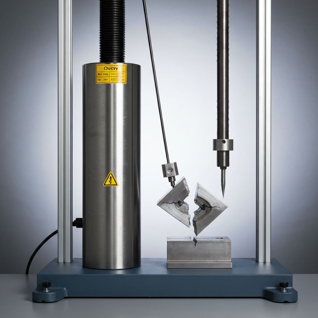
- Impact toughness: Charpy V-notch testing may be required for low-temperature service
- Impact requirements: Minimum impact energy at service temperature specified
- Transverse samples: Impact tests from qualification coupons or production welds
- Cold weather welding: Preheat and interpass temperature control critical
- Wind protection: Enclosures may be required to prevent rapid cooling
- Humidity effects: Moisture pickup in flux affects hydrogen content in weld
- Corrosive environments: Corrosion-resistant materials or coatings required
- Hydrogen cracking risk: Increases in high-strength steels; preheat/PWHT controls
- Low-hydrogen processes: GMAW solid wire, FCAW low-H flux, GTAW reduce hydrogen
- Flux-type selection: Low-hydrogen flux (H4, H5 classifications) minimizes risk
- PWHT (post-weld heat treatment): Stress relief reduces residual stresses and improves toughness
- Through-thickness properties: Z-direction ductility important for thick sections
- Lamellar tearing: Through-thickness shrinkage stresses + hydrogen + low ductility
- Through-thickness testing: May be required for critical thick sections under loading
- Weathering steel (A588): Filler metal must match base metal composition
- Stainless steel: Filler metals selected for corrosion and mechanical property matching
- Corrosion testing: Salt spray or accelerated testing may be required for verification
- Environmental qualification: Design review ensures weld requirements match service conditions
- Service temperature: Toughness requirements increase for low-temperature applications
- Seismic design: Enhanced inspection and testing for seismic-resistant moment connections
Conclusion
AWS D1.4 structural steel welding quality control is essential for ensuring structural integrity and safety through rigorous welder and procedure qualification, comprehensive visual and non-destructive testing, quantified acceptance criteria, and detailed documentation. Proper implementation of qualification requirements, inspection procedures, acceptance criteria, repair protocols, and documentation practices ensures that all structural welds meet design requirements and maintain structural adequacy. Quality control oversight throughout fabrication and construction identifies defects early, enables corrections before installation, and creates complete documentation supporting warranty, performance verification, and future investigations. VSG provides comprehensive structural welding inspection services including visual inspection by Certified Welding Inspectors, coordination of non-destructive testing (ultrasonic, radiography, magnetic particle), quality control oversight and documentation, defect evaluation and repair coordination, compliance verification, and consulting on AWS D1.4 implementation. Our inspection services ensure fabricated structures meet design specifications and AWS D1.4 compliance. Contact our team to discuss welding quality control procedures, inspection planning, acceptance criteria development, and compliance strategies for your structural steel projects.
Related Testing Services
- Ultrasonic Weld Testing
- Radiographic Testing
- Visual Inspection
- Magnetic Particle Testing
- Tensile Testing of Welds
Applicable Standards
Professional Engineering Support
This testing and verification work is part of comprehensive construction management and quality assurance services provided by our architectural and engineering consulting team. We support project management, quality control, and commissioning across military, nuclear, infrastructure, and commercial sectors.
Request Engineering Services