Core sampling involves drilling cylindrical specimens from hardened concrete structures to assess in-situ strength, quality, and durability. It's performed when cube test results are questionable, for forensic investigations of suspected failures, structural assessments of existing buildings, evaluation of suspect concrete or construction defects, and verification of concrete quality in dispute situations. Core testing provides the most reliable and definitive measure of actual concrete strength and properties in the structure, directly capturing concrete that was placed and cured under real construction conditions. Unlike laboratory companion cube samples which are cured in controlled environments, cores represent the actual concrete in service with its real moisture content, curing history, age, and environmental exposure. Core testing enables evaluation of concrete uniformity across the structure, detection of voids or honeycombing, assessment of segregation, identification of reinforcement corrosion, and forensic investigation of structural failure or performance issues.
When Core Sampling is Required
Core testing is necessary in multiple scenarios where concrete quality assessment is critical and potentially disputes the adequacy of construction or performance. When cast cube tests fail to meet specified strength requirements (e.g., 28-day cube strength below design specification), investigation is required to determine whether the structure is adequate despite test failures or remediation is necessary—core sampling directly measures in-situ concrete strength under actual curing and service conditions, providing definitive evidence superior to laboratory cube testing. When concrete placement procedures were questionable (improper vibration causing segregation, inadequate compaction, placement in adverse weather conditions, or extended set times), core sampling detects resulting quality issues and assesses structural adequacy. When fire or chemical damage is suspected (concrete exposed to high temperature, acidic attack, or aggressive environment), core sampling requires direct examination of damage extent through the full thickness, residual strength assessment, and evaluation of whether concrete can be maintained in service or requires replacement. When structural assessment of existing buildings is needed prior to modification, conversion to different use, or continued service in changed circumstances (e.g., increased loading), core testing establishes baseline concrete strength supporting structural analysis. When forensic investigation of failures, cracks, or performance issues is conducted to identify root causes—cores are examined petrographically to assess concrete composition, detect design defects, identify material deficiencies, and determine whether failures resulted from construction quality, design inadequacy, or material problems. When significant variability in companion cube results suggests placement problems (some cubes strong, others weak, indicating heterogeneous concrete placement), core sampling maps strength variation across the structure pinpointing weak zones. When concrete from different suppliers or batches needs comparison due to supplier changes or quality concerns, core sampling enables direct comparison of in-situ concrete from different sources. When concrete age or curing conditions are uncertain (e.g., contractor records questionable, construction timeline unclear, or accelerated curing procedures claimed), core sampling provides definitive strength data independent of cube records. In dispute situations where concrete quality is challenged by owner, contractor, engineer, or third parties and resolution requires definitive evidence, core testing provides objective, legally defensible results supported by internationally recognized standards (ASTM C42, EN 12504-1). Regulatory inspectors or enforcement agencies may mandate core testing to verify compliance with specifications or building codes. Insurance companies investigating damage or performance failures may require core testing to establish responsibility and liability for remediation costs. Lending institutions or asset purchasers may require core testing to verify condition of existing structures before commitment. Third-party quality audits or forensic reviews often include core sampling to independently verify contractor quality claims.
Core Extraction Procedure and Equipment
Cores are drilled using specialized diamond-tipped rotary core barrels with water cooling to prevent damage and control drilling temperature. The Hilti DD120 or DD250 drilling rigs are industry-standard equipment for structural concrete coring, providing the precision, stability, and control necessary for high-quality core extraction. Diamond core bits (such as Hilti Ultimate Diamond core bits) are designed for efficient concrete drilling with minimal damage to the sample through synthetic diamond impregnation in the cutting head. Diamond bits cut through concrete without shock damage and maintain consistent performance across concrete strengths from 20 MPa to 80+ MPa. The diamond matrix composition varies with concrete hardness—softer concrete requires harder matrix, harder concrete requires softer matrix—enabling bit selection appropriate for expected concrete properties. Standard core diameters are 100mm or 150mm per ASTM C42 or EN 12504-1, with depth/length at least equal to diameter (typically twice diameter or 200mm minimum for accurate strength results); length-to-diameter ratio (L/D) of 2.0 or greater minimizes end-effect corrections to test results. Shorter cores (L/D 1.0-1.9) require correction factors per EN 12504-1 to adjust measured strength to equivalent standard dimensions—correction factors typically reduce measured strength 5-15% depending on L/D ratio. Cores with L/D <1.0 are generally unacceptable for strength testing. Core extraction locations are strategically chosen to avoid major reinforcement where possible to prevent core breakage during drilling or sample handling and to minimize structural impact; however, reinforcement can be carefully drilled through if necessary, with detailed documentation and adjustment of strength results to account for reinforcement presence. Pre-drilling surveys using electromagnetic cover meters or ground-penetrating radar (GPR) identify reinforcement location, depth, and orientation, enabling core locations to be planned to avoid major steel where practical—typically 75-150mm lateral distance from reinforcement provides safe clearance. The drilling operator must be highly experienced and specially trained to maintain proper drilling speed (typically 100-400 RPM depending on concrete hardness and bit size), control water flow to prevent core damage (excessive water flow causes hydraulic shock, insufficient flow permits overheating), avoid vibration or impact that could create micro-cracking in the specimen, and properly extract the core without lateral stresses that could fracture the sample. Drilling pressure must be carefully controlled—light pressure with high speed for strong concrete, higher pressure with lower speed for weak concrete—excessive pressure creates heat and overstress, insufficient pressure wastes time and bits. Over-drilling through the core location weakens the extracted sample and creates stress concentration, so drilling must stop precisely when the core is fully separated from surrounding concrete. Under-drilling may leave the core bonded in the structure requiring destructive extraction with pry-bars or cutting tools, damaging the sample. A specialized core extraction tool (removing tube or coring tube) is often used to gently extract the core without lateral loading. Water-cooled diamond drilling perpendicular to the concrete surface is maintained at controlled rotation speeds and feed rates throughout extraction—too-high speeds generate excessive heat risking thermal damage and micro-cracking in the sample, too-low speeds cause excessive bit wear, bit glazing (diamonds becoming smooth and losing cutting effectiveness), and slow inefficient progress. Adequate water cooling at consistent flow rates (typically 10-30 L/min depending on bit size and drilling rate) is absolutely essential to dissipate drilling heat, transport cuttings away from the drilling interface, and prevent micro-cracking or thermal damage that would compromise test results. Core extraction typically requires 30 minutes to 2 hours depending on concrete strength, depth required, and equipment setup. Cores must be extracted perpendicular to the concrete surface (nominally 90° from surface) throughout the drilling operation to ensure uniform diameter and proper end-face development. Deviation from perpendicular creates tapered cores with non-parallel end faces, requiring extensive grinding for preparation and reducing usable sample length. Careful documentation of core extraction location, depth, orientation, and extraction method is essential for later interpretation. Each core is immediately labeled after extraction with the location, date, time of extraction, depth in structure, and orientation (typically marked with paint or tags), preventing sample mix-up and enabling correlation with structural drawings and results. Cores are wrapped and protected during transport and storage to prevent moisture loss, contamination, or physical damage. Cores should be tested within 7 days of extraction when possible, as concrete properties may be affected by extended time between extraction and testing.
- Hilti DD120/DD250 core drilling rig with Hilti Ultimate Diamond core bit equipment standard
- Diamond core bit composition: Synthetic diamond impregnation; bit matrix hardness selected for concrete strength
- Standard diameters: 100mm or 150mm per ASTM C42 or EN 12504-1 specifications
- Minimum length: Equal to diameter (L/D ≥1.0); preferably 2×diameter (L/D ≥2.0) for accurate results
- L/D ratios: <1.0 unacceptable for testing; 1.0-1.9 requires correction factors; ≥2.0 minimizes corrections
- Correction factors: EN 12504-1 provides adjustment for L/D <2.0; typically 5-15% strength reduction
- Pre-drilling survey: Electromagnetic cover meters or GPR to map reinforcement and plan locations
- Reinforcement avoidance: Locate cores 75-150mm from major reinforcement where possible for safety
- Through-reinforcement drilling: Possible with careful planning and strength result adjustment documentation
- Drilling speed: 100-400 RPM depending on concrete hardness and bit diameter; monitored throughout
- Rotation rate: Too high causes overheating; too low causes bit glazing and slow progress
- Drilling pressure control: Light pressure high speed for strong concrete; higher pressure lower speed for weak
- Water cooling: 10-30 L/min flow rate depending on bit size and drilling rate; absolutely essential
- Water function: Heat dissipation, cutting transport, thermal damage prevention in specimen
- Perpendicular drilling: Maintain 90° angle to concrete surface throughout extraction for uniform diameter
- Over-drilling prevention: Stop drilling when core fully separated to avoid weakening and stress concentration
- Core extraction: 30 minutes to 2 hours typical depending on strength, depth, and equipment setup
- Extraction method: Specialized coring tube or removal tool to extract without lateral stresses
- Experienced operators: Highly trained personnel essential for sample quality and specimen integrity
- Immediate labeling: Mark cores immediately with location, date, time, depth, and orientation after extraction
- Sample protection: Wrap and protect during transport and storage; prevent moisture loss or contamination
- Testing timing: Test within 7 days of extraction when possible to maintain concrete properties
Sample Preparation and Strength Testing
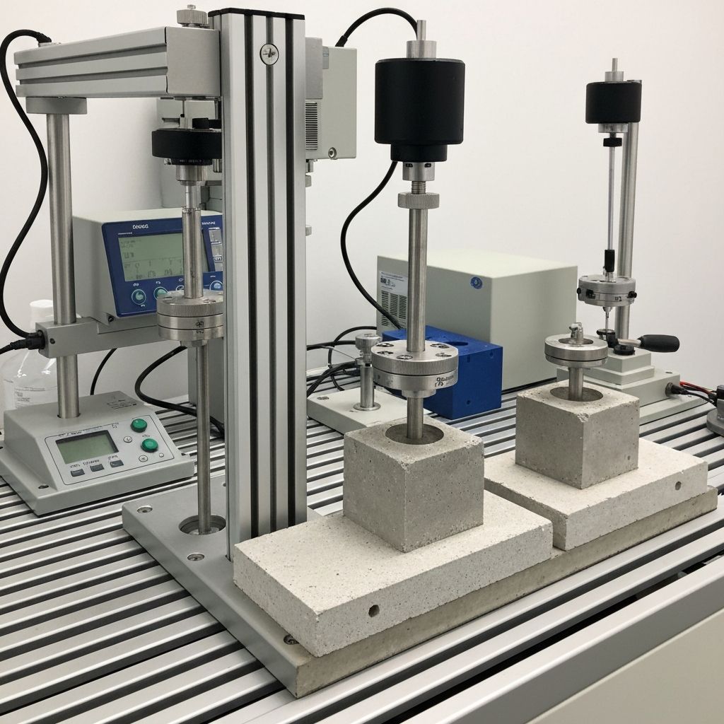
Cores must be properly prepared before testing to ensure accurate and representative strength results reflecting true in-situ concrete performance. Preparation includes careful cutting and grinding of both end faces perpendicular to the core axis using specialized diamond-tipped cutting equipment (typically water-cooled concrete saws with diamond-impregnated cutting blades designed for precision end-face preparation). End faces must be flat and smooth with surface irregularities not exceeding 0.5mm per EN 12504-1, creating uniform bearing and stress distribution during compression testing—irregular or non-perpendicular ends create stress concentrations causing falsely reduced measured strength and scatter in results. The required flatness tolerance is critical: deviation exceeding 0.5mm creates edge stresses that reduce measured strength up to 5-10% or more depending on severity. Both end faces are typically ground to achieve perpendicularity tolerance of ±1° to core axis (or ±0.5mm total deviation per face per EN 12504-1). Grinding removes surface irregularities from the drilling process and any cracks or damage created during core extraction and handling. Some standards permit sulphur capping or epoxy resin capping on one or both end faces instead of grinding, compensating for minor end irregularities; however, grinding directly on concrete is generally preferred for more uniform behavior. Length-to-diameter ratio (L/D) significantly affects measured compressive strength—the standard test configuration specifies L/D = 2.0 (e.g., 100mm diameter core with 200mm length). Shorter cores exhibit increased measured strength due to end effect: friction between concrete and testing machine platens constrains lateral expansion (Poisson effect), increasing lateral confinement and apparent strength. EN 12504-1 and ASTM C42 provide empirical correction factors for L/D ratios from 1.0 to 2.0, accounting for the measured strength increase from reduced sample length. Correction factors typically reduce strength 5-15% depending on L/D ratio—for example, L/D = 1.25 might require 9% downward correction, L/D = 1.5 requires 5% correction. Cores with L/D <1.0 are generally not acceptable for strength testing per standards. The prepared core is carefully inspected visually before testing for discontinuities affecting test interpretation and result reliability: visible honeycombing (large voids indicating poor consolidation or segregation), vertical voids or planes of weakness suggesting cold joints or segregation, surface quality issues indicating paste deficiency, and visible cracks suggesting freeze-thaw or chemical damage. High-quality uniform appearance with good consolidation and grey/cream paste color supports confidence in strength results. Presence of visible defects may explain low strength results and should be documented in testing reports for context. Moisture condition of the core at testing significantly affects measured compressive strength and must be carefully controlled and documented. EN 12504-1 specifies testing in the saturated surface-dry (SSD) condition—core surface damp but no free water standing on surface—as the standard test condition. Cores tested in the dry condition (oven-dried to constant mass at 105°C typically show 5-10% higher strength than SSD condition due to moisture effects on paste hydration and microstructure. Cores tested in fully saturated condition (pores completely filled with water) show 5-10% lower strength than SSD due to reduced internal friction and altered stress transfer. The actual in-situ moisture state of concrete in the structure is typically intermediate between dry and saturated, varying with exposure conditions (sheltered vs. wet exposure, depth in structure, etc.). Measured strength must be interpreted considering actual service moisture conditions—strength measured in dry condition may not represent strength under service conditions where concrete is partially or fully saturated. Moisture condition adjustment factors are available to estimate strength under service conditions. Compression testing per EN 12504-1 is performed on a calibrated hydraulic compression testing machine (minimum 2000 kN capacity typical for 100-150mm cores). The prepared core is centered in the machine between steel platens with load applied axially at controlled rate (typically 0.5-1.0 MPa/sec) until failure. Load-displacement curve is recorded showing stiffness and failure mode. Failure load is recorded in Newtons, and compressive stress is calculated as: Stress (MPa) = Load (N) / Core Area (mm²). Failure mode is documented: brittle sudden failure typical of high-strength concrete, or gradual progressive failure typical of lower-strength concrete. Multiple cores (minimum 3 per test location per EN 12504-1) are tested to establish average strength and variability. Statistical analysis identifies outliers—cores with anomalously high or low results potentially due to core damage, preparation issues, or local concrete defects. A coefficient of variation (standard deviation / mean) >10% typically indicates significant concrete variability or testing issues requiring investigation. Core results are reported as individual strength values, average strength, standard deviation, and number of cores tested. Compressive strength units are typically MPa (megapascals) in metric or psi (pounds per square inch) in imperial units. Strength development with concrete age is considered—younger concrete (first 90 days) typically shows continued strength development, while mature concrete (>1 year) typically shows stable plateau strength (except for very slow hydration in heavily sealed or thick sections).
- End face preparation: Cut both ends perpendicular to core axis using water-cooled diamond saw
- Surface flatness: Maximum 0.5mm deviation tolerance per EN 12504-1 for uniform bearing stress
- Perpendicularity: ±1° to core axis or ±0.5mm total deviation per face typical tolerance
- Grinding method: Diamond-impregnated grinding wheels or capping resin compensation permitted
- Flatness importance: Deviation >0.5mm creates edge stress and 5-10%+ strength reduction
- L/D ratio impact: L/D = 2.0 standard; shorter samples show higher apparent strength from end effect
- Correction factors: EN 12504-1 provides adjustments for L/D 1.0-2.0; typically 5-15% downward
- L/D = 1.25 example: Approximately 9% strength reduction correction applied
- L/D = 1.5 example: Approximately 5% strength reduction correction applied
- L/D <1.0 unacceptable: Generally not permitted by standards for strength testing
- Visual inspection: Examine for honeycombing, voids, cracks, or segregation planes pre-testing
- Quality appearance: Uniform grey/cream paste color indicates good consolidation
- Defect documentation: Note visible defects in reports for context on results
- Moisture condition: Saturated surface-dry (SSD) is standard test condition per EN 12504-1
- Dry strength: 5-10% higher than SSD condition; represent worst-case scenario
- Saturated strength: 5-10% lower than SSD condition; represents wet exposure
- Service moisture: Typically intermediate between dry and saturated; affects in-situ strength
- Adjustment factors: Available to convert test strength to estimated service condition strength
- Compression machine: Minimum 2000 kN capacity typical for 100-150mm cores
- Loading rate: Typically 0.5-1.0 MPa/second controlled rate to failure
- Load recording: Load-displacement curve recorded; failure load documented in Newtons
- Stress calculation: Compressive stress = Load (N) / Core Area (mm²); reported in MPa or psi
- Failure mode: Document brittle vs. progressive failure indicating concrete type/strength
- Minimum replicates: 3 cores per location minimum; more for high-variability concrete
- Outlier evaluation: Coefficient of variation >10% indicates variability or testing issues
- Average strength: Statistical analysis of multiple cores determines representative value
- Age consideration: Concrete <90 days may show continued strength development with time
- Age >1 year: Typically shows stable plateau strength absent continued hydration
Assessment and Reporting
Core test results are compared with design strength requirements after applying appropriate conversion factors (L/D corrections, moisture adjustments) to estimate equivalent standard cube strength. A minimum of three cores per investigation area is recommended to establish average strength and evaluate variability; more cores (5-10) are often tested for large areas or when significant variability is expected. Results show considerable variability due to concrete heterogeneity, local consolidation differences, segregation patterns, and exposure conditions. Statistical analysis identifies outliers—cores with anomalously high or low results potentially due to core damage, preparation issues, or genuine local concrete defects. Coefficient of variation (standard deviation divided by mean) greater than 10% typically indicates significant concrete variability or potential testing/preparation issues requiring investigation. Average strength is compared to design concrete strength specification (e.g., 25 MPa, 30 MPa at 28 days). Comprehensive reports document core locations with exact coordinates and marked locations on structure photographs, visual observations during coring (drilling difficulty, water infiltration, spalling, reinforcement encountered), core visual condition (honeycombing, voids, cracks, color, paste quality), preparation methods used, test results (individual core values, average, standard deviation, coefficient of variation), moisture condition at testing (dry, SSD, saturated), age of concrete at testing and estimated placement date, and structural adequacy assessment. For strength below specification, assessment determines whether: (1) concrete is still adequate for intended use at reduced strength with factor of safety evaluation; (2) immediate remediation is necessary such as temporary supports, load restrictions, or additional reinforcement; (3) full removal and replacement is required; or (4) specialized testing or structural analysis is warranted to evaluate actual structural performance. Comparison with companion cube results is performed if available—differences between core and cube results indicate construction quality issues. Typically, cores show 10-20% lower strength than corresponding cubes due to in-situ curing conditions, age differences, and construction variables. Cores much lower than cubes (>25% reduction) suggest serious construction quality problems. In disputes, the core strength is considered more reliable evidence of actual structural capacity than cube results. Cores may also be used for additional testing beyond compressive strength: petrographic analysis (microscopic examination of aggregate types, paste quality, pore structure, cracks, segregation); chloride content testing (per EN 14629) to assess chloride penetration depth and corrosion risk; carbonation depth testing (per EN 14630) to evaluate pH profile and reinforcement protection; water absorption and permeability testing (per EN 12504-1 or EN 1015-18) to assess durability; and visual assessment of reinforcement corrosion around cored location by visual inspection. Photographic documentation of extracted cores before and after cutting, end-face condition, and any visual anomalies provides additional evidence. Historical comparisons may be made if earlier cores exist from the structure showing strength changes with time. Accelerated concrete aging models may estimate long-term durability if early-age cores show rapid strength gain or development trends.
Core Location Planning and Structural Impact Considerations
Strategic planning of core locations is essential to obtain representative samples while minimizing structural impact and damage. Cores should be located in accessible areas where removal will not compromise structural integrity or aesthetics. High-importance structural elements (main beams, columns carrying substantial load, load-bearing walls) are typically avoided unless absolutely necessary; secondary elements (floor slabs, non-load-bearing walls, parapets) are preferred when representativeness permits. Cores should be distributed across the area of concern to capture spatial variability in concrete quality—cores should be taken from multiple levels (top, middle, bottom of pours), different distance from edges, and locations experiencing different consolidation challenges. For floor slabs, cores may be taken from center areas (typically best consolidation) and near beam or column locations (typically more difficult consolidation). For walls, cores from mid-height (best consolidation) and near base (potential accumulation of paste/segregation) provide contrast. Cores should be taken at locations without significant reinforcement where practical to avoid structural compromise—typically 300-600mm from concentrated reinforcement clusters. When cores must be taken through reinforcement, small bars can be cut if necessary with careful documentation; large primary bars should be avoided. After core extraction, cored holes must be appropriately repaired: small holes in non-structural elements may be left open or filled with non-structural grout; holes in structural elements must be properly repaired with approved repair material (typically structural concrete repair mortar or epoxy injection) to restore capacity. Repair design should maintain or restore original strength; cores in critical load paths may require engineered repair procedures. Cored holes in exposed concrete surfaces should be repaired to restore appearance. Cored holes in reinforcement-critical locations require careful evaluation to verify remaining reinforcement is adequate.
Interpretation of Results and Comparison with Specifications
Core strength results must be interpreted in context of multiple factors beyond simple comparison to specification. Design specification typically defines 28-day strength (or sometimes 56 or 90-day strength) in controlled curing conditions. Cores extracted at later ages (3 months, 1 year, or longer after placement) may show higher strength than design specification if concrete continues strength development (particularly in thick sections or sealed concrete where hydration continues). Age adjustment equations (such as RILEM or ACI models) can estimate equivalent 28-day strength from older concrete, normalizing results for comparison to specification. Curing conditions of actual concrete often differ from specification assumptions: standard laboratory cube curing (20±2°C, 95±5% RH) is ideal, but field concrete experiences variable temperature (potentially cooler in winter, warmer in summer), variable humidity (potentially dry in windy or heated conditions, damp in rain or below-grade), wind exposure (increasing drying rate), and access to sunlight (increasing temperature). These variations typically reduce in-situ strength 10-20% compared to ideal laboratory curing. Cool curing conditions (below 10°C) dramatically slow hydration and strength development. Hot curing conditions (above 25°C) accelerate early strength gain but may reduce long-term strength. Proper assessment requires understanding actual curing conditions when concrete was placed. When core strength is below specification, several interpretations are possible: (1) If only slightly below specification (5-10%), concrete may still be structurally adequate when evaluated against actual applied loads with appropriate safety factors—strength is a design parameter with inherent safety factors (typically 1.4-1.6 for reinforced concrete design); (2) If significantly below specification (>15%), remediation is typically required such as structural reinforcement, increased support, or removal and replacement; (3) If only limited cores are tested showing weak results but other cores are strong, localized defects or construction issues may be indicated rather than general deficiency; (4) Presence of visible defects (honeycombing, segregation, poor consolidation) correlates with low strength and indicates potential quality problems. Comparison with companion cube results (if available) provides context: if cores are similar to cubes, then specification may have been inadequate or materials/curing conditions were poor uniformly; if cores are significantly lower than cubes, field conditions were worse than laboratory. For disputes, legally defensible assessment considers: (1) measured strength values with full documentation; (2) comparison to design requirements with stated assumptions; (3) assessment of structural adequacy using actual loads and measured strength; (4) investigation of cause of any deficiency; (5) recommended remediation or continued service assessment; (6) professional judgment and compliance with applicable standards and codes.
Conclusion
Core sampling and in-situ strength testing provide the most definitive method for assessing concrete quality in existing structures, resolving disputes over concrete adequacy, and supporting forensic investigations of performance issues. Proper execution of core extraction, preparation, testing, and interpretation requires specialized equipment (Hilti DD120/DD250 drilling rigs with Hilti Ultimate Diamond core bits), trained personnel, and adherence to international standards (EN 12504-1, ASTM C42, EN 13791). Core results directly measure concrete strength under actual service conditions, providing superior evidence compared to laboratory companion cubes. When questions arise about structural concrete quality, suspected construction defects, performance failures, or concrete strength disputes, our experienced team provides precise core extraction, comprehensive testing, detailed assessment, and expert interpretation supporting informed decisions about structural adequacy and remediation strategies. We provide independent third-party core testing services with CWI-level quality oversight and professional structural engineering analysis. Contact our team to discuss core sampling planning, testing procedures, and technical consulting for your structural assessment needs.
Related Testing Services
- Compressive Strength Testing
- Rebound Hammer Testing (Schmidt Hammer)
- Ultrasonic Pulse Velocity Testing
- Petrographic Analysis
- Chloride Content Analysis
- Carbonation Depth Testing
- Half-Cell Potential Testing
Applicable Standards
Professional Engineering Support
This testing and verification work is part of comprehensive construction management and quality assurance services provided by our architectural and engineering consulting team. We support project management, quality control, and commissioning across military, nuclear, infrastructure, and commercial sectors.
Request Engineering Services